background image

20

Q-Link

Q-Link allows the television to communicate with a compatible VCR or DVD Recorder.

For Q-Link communication to work, the TV must be connected to a recording device with the “Q-Link”, “NEXTVIEWLINK”,
“DATA LOGIC”, “Easy Link”, “Megalogic” or “SMARTLINK” logo using a “fully wired” Scart cable between the AV2 /
AV4 terminal of the television and the appropriate terminal on your VCR or DVD Recorder.
For connection to the appropriate Scart terminal on the recording device, refer to the device’s instruction book.

When using a “NEXTVIEWLINK” device the main features possible are the following :

Preset Download

This allows the programme order from the TV to be downloaded to the recording device, helping to ensure that correct
recordings are made; there are several ways to perform this operation :
1. During installation as explained in the “Quick Start Guide” on page 8, 9.
2. When Auto setup is started from within the Tuning menu. See page 15.
3. Preset download started from the recording device, refer to the device’s instruction book.

Important Note:

Not all recording devices support this type of data communication system. Some may support certain features, but not
others. Refer to the recording device’s instruction book.
If Q-Link is inoperative, first confirm that your Scart cable is a “fully wired” type. Ask your dealer for further details.

The recording device is recording the programme signal
from its own tuner. If you wish you can switch off the TV
and leave the device recording in the normal way.

The tape or disc may have been “write protected”, missing
or may be damaged. The device may already be
recording.
Refer to the device’s instruction book.

Additionally, when using a “Q-Link” device the main features possible are the following :

The following features are only available from the device connected to the Scart terminal selected using “Q-Link”. See
page 14.

TV / Recording device Auto Power On

If you insert pre-recorded media into the recording device and press the Play button whilst the TV is in  Standby mode,
the TV will automatically switch on and select the correct AV input so that you can view the content.

Recording device Auto Power Standby

When the TV is switched into Standby mode, the recording device will also switch into Standby mode if there is no
media inserted, or if there is media inserted and the device is in Rewind or Stop mode. If a VCR is rewinding a tape,
it will not switch into Standby mode until rewinding has finished.

Recording device Image View On

If the TV is in Standby mode and the recording device sends a menu to be displayed on the TV screen (e.g., Main
menu), the TV will automatically switch On and the menu will be displayed.
Some other devices may support this feature. Refer to the device’s instruction book.
This TV will also communicate with other recording device’s that bear the following logos :
• “DATA LOGIC” (a trademark of Metz Corporation)

• “Megalogic” (a trademark of Grundig Corporation)

• “Easy Link” (a trademark of Philips Corporation)

• “SMARTLINK” (a trademark of Sony Corporation)

Important Note:

These recording devices may support some or all of the above functions.
Not all recording devices support this type of data communication system. Somemay support certain features, but not
others. Refer to the device’s instruction book. Some features are only available from the device connected to the Scart
terminal selected using “Q-Link”. See page 14.
If Q-Link is inoperative, first confirm that your Scart cable is a “fully wired” type. Ask your dealer for further details.

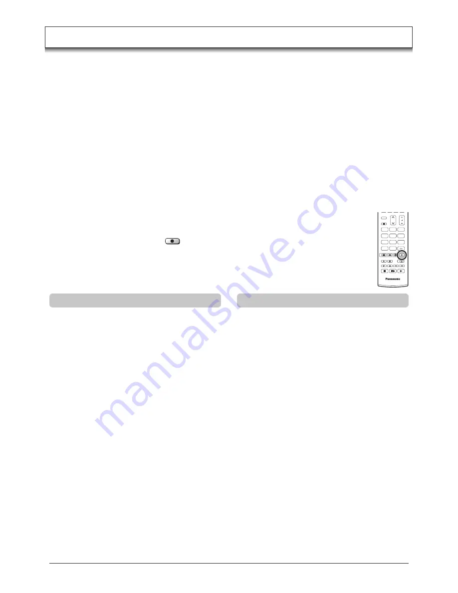
What You See Is What You Record (DIRECT TV RECORDING)

This will allow the immediate recording of the programme currently shown on the TV, by the recording
device attached to the Scart terminal, which can be chosen using “Q-Link”.  See page 14.

Press the 

DIRECT TV REC

 button.   

DIRECT TV REC

If the recording device is in Standby mode with usable recording media inserted, it will automatically
switch on when you press the 

DIRECT TV REC

 button.

If a “Q-Link” device is connected, a message will appear on the TV screen showing what is being
recorded, or if it is not possible to record. Some “Q-Link” compatible devices will only display the message
when on the VCR programme position(0) or in AV mode. Refer to the device’s instruction book.

TV

1

2

3

4

5

6

7

8

9

C

0

N

Recording in progress

No recording -Check tape or disc

Summary of Contents for TH-37PA30

Page 1: ... Instructions Progressive Plasma Television Model No 1 N 2 3 4 5 6 7 8 9 C 0 TQBC0711 Please read these instruction before operating your set and retain them for future reference English Pedestal stand shown above is optional extra ...

Page 2: ...14 Tuning menu overview 15 Tuning menu Programme edit 16 Adding deleting a programme channel 16 Moving a programme channel 16 Tuning a programme channel 16 Renaming a programme channel 17 Locking a programme channel 17 Changing the sound system for a channel 17 Copying programme information to a recording device 17 Tuning menu Auto setup 18 Tuning menu Manual tuning 19 Manual tuning via front pane...

Page 3: ... plug will only fit an earthing type power outlet This is a safety feature If you are unable to insert the plug into the outlet contact an electrician Do not defeat the purpose of the earthing plug To prevent electric shock ensure the grounding pin on the AC cord power plug is securely connected Symptoms After images appear CAUTION Trademark Credits VGA is a trademark of International Business Mac...

Page 4: ...ce in image sound etc In particular keep video equipment away from this product When using the Plasma TV The Plasma TV is designed to operate on 220 240 V AC 50 60 Hz Do not cover the ventilation holes Doing so may cause the Plasma TV to overheat which can cause fire or damage to the Plasma TV Do not stick any foreign objects into the Plasma TV Do not insert any metal or flammable objects into the...

Page 5: ... power cord plug the resultant humidity can damage the insulation which could result in fire Pull the power cord plug out from the wall outlet and wipe the mains lead with a dry cloth This Plasma TV radiates infrared rays therefore it may affect other infrared communication equipment Install your infrared sensor in a place away from direct or reflected light from your Plasma TV The front of the di...

Page 6: ...battery types i e Alkaline and Manganese or use rechargeable Ni Cad batteries Fitting remote control batteries Check that you have the accessories and items shown Accessories Operating Instruction book TQBC0711 Ferrite core Large size 2 Ferrite core Small size 5 Batteries for the Remote Control Transmitter 2 R6 UM3 size Mains Lead Installing the ferrite core Small size Pull back the tabs in two pl...

Page 7: ...able to the TV s Scart terminals connect through this window This window cannot close completely when connecting the Scart cable Other cables should be connected before closing the terminal cover 1 2 1 2 Fastening method Fastening of Mains Lead and other cables Fastening band Fastening To tighten Loosening Pull off Keep the knob pressed Fastening method of other cables Attach the clamper on the in...

Page 8: ...f it was switched to Standby mode Note This TV will still consume some power as long as the mains plug is still inserted into the wall socket Power Indicator Remote control signal sensor LED Indicator Standby Red On No Light TV 1 2 3 4 5 6 7 8 9 C 0 OK N 2 1 Connect the mains lead to the Plasma TV 2 Connect the mains plug to the wall socket 2 1 C A T S sensor Plasma C A T S Contrast Automatic Trac...

Page 9: ...k compatible recording device you can now switch it On Downloaded tuning data will match the television s Not all devices support this download of programme information some may require to be started manually See the device s instruction book for details If the recording device has not accepted download data from the TV you may need to select the download option from the device s menu If Q Link is...

Page 10: ...When in Standby mode switches TV On Switch between viewing TV or AV input see page 36 Cursor buttons to make selections and adjustments Photo View mode button see page 28 31 Exit the mode MULTI WINDOW button see page 24 25 Volume up down button Press to store settings in Sound menu Tuning menu and Teletext or to change between Multi and Single mode during Photo View mode Increases or decreases the...

Page 11: ...cursor and select menus The left and right cursor buttons are used to access menus adjust levels or to select from a range of options The OK button is used with a number of features to store settings after adjustments have been made or options have been set The EXIT button is used to exit the menu system and return to the normal viewing screen An On Screen Help box is displayed whenever a menu is ...

Page 12: ...z signals Tint is displayed Allows you to set the overall colour tone of the picture Choose from Cool Normal and Warm Automatically reduces unwanted picture noise Reduces MPEG noise Allows you to choose from Off Min Mid and Max This function is effective in reducing the digital block noise when viewing DVD VCD or digital broadcasting The effect will be changed based on the scene and image Note MPE...

Page 13: ...Stereo to provide the best reproduction but if reception deteriorates or if the service is not available then switch to Mono Mono M1 and M2 can also be selected if a mono signal is being transmitted Sound quality can be improved when watching music scene or drama by selecting the appropriate Music or Speech mode To enjoy a concert hall effect turn Ambience On Switching is also possible by pressing...

Page 14: ...to choose from Off Low Mid and High Do not display a picture in 4 3 14 9 Picture out of picture Picture and picture Picture and text modes for an extended period as this can cause an after image to remain on the side panels either side of the display field To prevent the appearance of such an after image illuminate the side panels By reducing the brighness of picture power consumption can be lower...

Page 15: ... level varies significantly between stations Adjusting one station s volume to bring it into line with the other stations means you can avoid having to adjust the volume each time you change channels This option is used when a decoder is connected via AV2 AV4 Store the setting as On so that every time this programme position is selected the TV software is set to handle the decoded information this...

Page 16: ...amme edit Prog Chan Name Lock Sys 1 2 3 4 5 CH44 CH51 CH41 CH47 CH37 Off Off Off Off Off SC1 SC1 SC1 SC1 SC1 ABC XYZ FTP 123 456 Green Red Make sure the cursor is in the Prog column Press the Yellow button Choose the new position for the programme channel Press the Yellow button again to confirm your decision Yellow Confirm Cancel Programme edit Prog Chan Name Lock Sys 1 2 3 4 5 CH44 CH51 CH41 CH4...

Page 17: ...Off SC1 SC1 SC1 SC1 SC1 OK Changing the sound system for a channel You can change the sound system used for a programme channel Move to the Sys column Choose the required sound system SC1 PAL B G H SECAM B G SC2 PAL I SC3 PAL D K SECAM D K F SECAM L L Press the OK button to store the new setting Programme edit Prog Chan Name Lock Sys 1 2 3 4 5 CH44 CH51 CH41 CH47 CH37 ABC XYZ FTP 123 456 Off Off O...

Page 18: ...art and complete the Auto setup procedure so that the TV is retuned Press to start Auto setup The TV will search for locate store and then sort into order your local stations If compatible recording device is connected via the AV2 AV4 terminal programme data will be sent to the device via Q Link See page 20 Once this operation is completed the TV will display the programme now stored on programme ...

Page 19: ...o change programme position or start search When the desired station is found press the STR button to store The programme position will flash Repeat above procedure to tune additional programme positions Press the F button at any time to go back to watching TV Note When using a VCR without video and audio input output terminals it is convenient to connect the antenna cable as indicated in the inst...

Page 20: ...lect the correct AV input so that you can view the content Recording device Auto Power Standby When the TV is switched into Standby mode the recording device will also switch into Standby mode if there is no media inserted or if there is media inserted and the device is in Rewind or Stop mode If a VCR is rewinding a tape it will not switch into Standby mode until rewinding has finished Recording d...

Page 21: ...ience problems with the screen display size when playing back widescreen format recordings from your VCR then it is possible that the tracking control of your VCR requires adjustment your VCR instruction book will contain adjustment details The widescreen aspect ratios of different films and programmes can vary If these are wider than a standard 16 9 aspect picture then a black band may be visible...

Page 22: ...pand a 4 3 picture to fill the whole screen rather than watching a programme with black stripes down the left and right sides of the picture The 4 3 picture will be stretched horizontally so that the image fills the screen this is done in such a way that the stretching is only obvious at the left and right edges of the screen Just Just Just 4 3 will display a 4 3 picture at its standard 4 3 size w...

Page 23: ... Zoom2 Zoom2 Zoom2 will display 16 9 anamorphic letterbox pictures as a full screen display with no aspect distortions Zoom2 Zoom3 Zoom3 Zoom3 Zoom3 will display 21 9 letterbox pictures as a full screen display with no aspect distortions 16 9 will display the picture at its maximum size but with sligth stretching ...

Page 24: ...ayed Press the Blue button to swap the contents of the two windows Use the remote control to select a TV channel or an AV source to appear in the left window Picture and picture Allows two pictures to be viewed at the same time as picture in picture does The difference is how the two pictures are displayed in picture in picture the smaller window appears within the main picture in picture out of p...

Page 25: ...MULTI WINDOW button to move between viewing teletext and the picture and text feature Picture and text lets you see the current programme and a page of teletext side by side Whilst using this feature the remote control affects the teletext page if you wish to make changes to the programme viewed press the TV TEXT button to return to watching the programme on its own then make the desired changes P...

Page 26: ...ings On enables fine picture adjustment at a professional level Contrast Brightness Sharpness MENU EXIT Note Press the N button or press whilst the cursor is at the Normalise position to reset all settings to their default levels White balance Advanced settings Note Carry out W B adjustment as follows 1 Adjust the white balance of the bright sections using the W B High R and W B High B settings 2 ...

Page 27: ...Normalise position to reset all settings to their default levels MENU EXIT PC Menu Picture Signal Picture Pos Size Picture Pos Size Normalise H Size V Pos V Size Clock Phase H Pos Normal Sync H V To synchronize by the horizontal and vertical signals from your PC on G To synchronize by the green signal form your PC if available Signal During PC mode Press the MENU button Move to choose Signal Acces...

Page 28: ...ile hierarchy is displayed on the PC as shown below DCIM Folder The digital camera creates this folder automatically 100_PANA Folder Folder names consist of a 3 digit folder number which is followed by five arbitrary characters Digital camera images are stored within these folders JPEG files in the 100_PANA folder are displayed when a Card which is structured as shown left is inserted Notes The fo...

Page 29: ... confirm that a card is correctly inserted Press the SD button again to exit Photo View mode miniSD Card requires miniSDTM adapter The media listed in the right column above can be read via the PC Card in the PC Card adapter Hard disk PC Cards and other recorded media cannot be used Place the selected media onto the PC Card and then insert into the PC Card Slot When both SD Card and PC Card are in...

Page 30: ...et the overall colour tone of the picture Choose from Cool Normal and Warm Tint Colour balance Slide show Interval Sequence Repeat Card Provides access to Slide Show mode See page 31 When the Slide Show allows you to select the display intervals between 5 to 90 seconds When the Slide Show allows you to select the Order or Random When Repeat is On the Slide Show repeats automatically Select either ...

Page 31: ...he remote control OK Slide Show Slide show Interval Sequence Repeat Card Viewing setup Access 5Sec Order On PC Slide show Interval Sequence Repeat Card Viewing setup 5Sec Order On PC 12 images are displayed Press to select desired image Press the OK button to display Single mode OK Menu Single Select Exit PHOTO VIEW MODE 0001 0013 Filename 102 0001 Date 30 03 2002 Pixel 1600X1200 Multi mode A sing...

Page 32: ...by mode Press again to switch back on VCR DVD switch Use this switch to select whether controls operate the DVD equipment or VCR Play Press to playback the tape or DVD Stop Press to stop the tape or DVD Skip Fast Forward Cue VCR Press to fast forward the tape In Play mode press to view the picture rapidly forward Cue DVD Press once to skip to the next track Skip Rewind Review VCR Press to rewind t...

Page 33: ...ratio is set to 16 9 TV Teletext mode Press the TV TEXT button to switch between the current programme Page Selection Pages can be selected in two ways a Press the Up Down buttons to increase or decrease the page number by one b By entering the page number using 0 9 on the remote control Full Top Bottom Press the MENU button to display special functions followed by the Green button Press the Green...

Page 34: ...ge is found its number is displayed at the top of the page so that you may select it as more sub pages are picked up the display at the top of the page changes so that you are always offered the most recently transmitted selection of sub pages In Teletext operation use the following procedure to access sub pages If the sub page you want to look at is not yet available press the MENU button to disp...

Page 35: ...ges to be found The sub pages found will be displayed across the top of the screen When the page is available press the Yellow button to view the page Regardless of how many pages are found pressing the Yellow button will take you to the sub page which you requested Press the TV TEXT button to return to normal TV operation INDEX When in TOP operation Press the INDEX button to return to the main in...

Page 36: ...after a few seconds If you want to select an input when the keys are not shown press the TV AV button again and the keys will reappear Notes The volume level of the headphones can be adjusted by selecting Headphone volume from the Sound menu Additional equipment and cables shown are not supplied with this TV set Notes You can also select an AV source using the TV AV button on the front panel of th...

Page 37: ... not connect a computer with TTL output 5V to this set For Scart terminal wiring information see page 40 When a Monaural VCR is used connect the Monaural Audio cable to the Audio L Left terminal How to connect the Audio Output terminals How to connect the AV1 2 4 Scart terminals How to connect the Component Input terminals Amplifier to Speaker System AV1 VCR SET TOP BOX DVD PLAYER DVD RECORDER CAM...

Page 38: ... not be possible to show fine detail with sufficient clarity The PC input terminals are DDC1 2B compatible If the computer being connected is not DDC1 2B compatible you will need to make setting changes to the computer at the time of connection Some PC models cannot be connected to the set There is no need to use an adapter for computers with DOS V compatible D sub 15P terminal The computer shown ...

Page 39: ...ymptoms Some parts of the screen do not light up After images appear Notes External surfaces of the unit may become hot during operation But this is completely normal See label on the base of this equipment for ratings and other information Plasma TV panel Check The plasma TV panel is manufactured using an extremely high level of precision technology however sometimes some parts of the screen may ...

Page 40: ... R CVBS in video Earth Earth Q Link data Status CVBS Audio in L Audio earth Audio in R AV2 Scart terminal VIDEO S VIDEO Q Link AV2 Pins 15 and 20 are dependent on AV2 S VHS VIDEO switching AV3 S VIDEO 4 pin terminal Luminance earth Luminance in Chrominance in Chrominance earth 21 19 17 15 13 11 9 7 5 3 1 20 18 16 14 12 10 8 6 4 2 Socket Earth CVBS out video CVBS earth Audio out L Audio out R CVBS ...

Page 41: ... 480 35 00 66 67 4 640 480 75 Hz 37 50 75 00 5 852 480 60 Hz 31 50 60 00 6 800 600 60 Hz 37 88 60 32 7 800 600 75 Hz 46 88 75 00 8 800 600 85 Hz 53 67 85 06 9 Macintosh16 832 624 49 73 74 55 10 1 024 768 60 Hz 48 36 60 00 11 1 024 768 70 Hz 56 48 70 07 12 1 024 768 75 Hz 60 02 75 03 13 1 024 768 85 Hz 68 68 85 00 14 Macintosh21 1 152 870 68 68 75 06 15 1 280 1 024 60 Hz 63 98 60 02 16 1 280 1 024 ...

Page 42: ... 2 0 5 Vrms Y 1 0 Vp p including synchronization PB PR 0 35 Vp p HIGH DENSITY D SUB 15PIN R G B 0 7 Vp p 75 Ω HD VD 1 0 5 0 Vp p high impedance SD Card slot 1 PC Card slot 1 21 Pin terminal Audio Video in TV out RGB in 21 Pin terminal Audio Video in Audio Video out S Video in Q Link 21 Pin terminal Audio Video in Audio Video out S Video in RGB in Q Link UHF VHF Temperature 0 40 C Humidity 20 80 RH...

Page 43: ......

Page 44: ...mer Record The model number and serial number of this product can be found on its rear panel You should note this serial number in the space provided below and retain this book plus your purchase receipt as a permanent record of your purchase to aid in identification in the event of theft or loss and for Warranty Service purposes Model Number Serial Number ...

Reviews: