


19
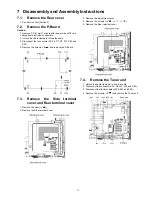
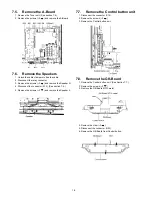
7.9.
Remove the SU-Board
1. Remove the flexible cables (SU1B, SU2B, SU3B and
SU4B) connected to the SU-Board.
2. Remove the flexible cable (SU11-SD11) and the bridge
connector (SC41-SU41).
3. Remove the molding prop (
×
1 ).
4. Remove the screws (
×
2 ,
×
2
) and remove the SU-
Board.
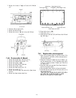
7.10. Remove the SD-Board
1. Remove the flexible cables (SD1B, SD2B, SD3B and
SD4B) connected to the SD-Board.
2. Remove the flexible cable (SU11-SD11) and the bridge
connectors (SC42-SD42 and SC46-SD46).
3. Remove the molding prop (
×
1 ).
4. Remove the screws (
×
2 ,
×
2
) and remove the SD-
Board.
7.11. Remove the SC-Board
1. Remove the SU-Board and SD-Board. (See section 7.9.
and 7.10.)
2. Unlock the cable clampers to free the cable.
3. Disconnect the connectors (SC2 and SC3).
4. Disconnect the flexible cable (SC20).
5. Remove the screws (
×
6
) and remove the SC-Board.
7.12. Remove the SS2-Board
1. Remove the Tuner unit. (See section 7.4.)
2. Disconnect the bridge connector (SS22-SS24) and dis-
connect the flexible cable (SS58).
3. Remove the screws (
×
2
) and remove the SS2-Board.
Summary of Contents for TC-P50X1
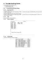
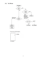
Page 15: ...15 6 4 No Picture ...
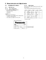
Page 25: ...25 8 1 4 Adjustment Volume Location 8 1 5 Test Point Location ...
Page 27: ...27 ...
Page 28: ...28 ...
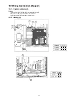
Page 34: ...34 10 3 Wiring 2 ...
Page 35: ...35 10 4 Wiring 3 ...
Page 36: ...36 10 5 Wiring 4 ...
Page 37: ...37 11 Schematic Diagram 11 1 Schematic Diagram Note ...
Page 69: ...69 A B C D E F G H I 1 2 3 4 5 6 P BOARD COMPONENT SIDE LSEP1279UNHB ...
Page 82: ...82 ...
Page 84: ...84 13 1 2 Accessories ...
Page 85: ...85 13 1 3 Mechanical Replacement Parts List ...
Page 88: ...88 13 2 Electrical Replacement Parts List 13 2 1 Replacement Parts List Notes ...


