TC-L47E50
16
7.4.
Panel Assembly
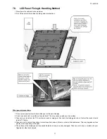
1. Place black tape in the position indicated, see detail 1.
2. Fit the panel to the cabinet, handling it extremely carefully. Fig A
3. Once the panel has been fitted to the cabinet, pull the panel towards the cabinet until it meets the stops.
4. Take extreme care not to knock the cabinet with the corners of the panel.
5. Stick the tape on top of the plate K cable, as indicated in Fig B.
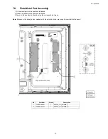
No.
Part Num.
Quant.
Description
1
L5EDDYY00362
1
LCD PANEL
Summary of Contents for TC-L47E50-1
Page 38: ...TC L47E50 37 Cables Clampers Tapes A B C D E F G H P4 LD GK4 P2 A02 SP R A12 SP L A12 A10 K10 ...
Page 39: ...TC L47E50 38 11 Schematic Diagram 11 1 Schematic Diagram Notes ...
Page 40: ...TC L47E50 39 11 2 A Board 1 17 Schematic Diagram 6 5 4 3 2 1 A B C D E F G H I ...
Page 41: ...TC L47E50 40 11 3 A Board 2 17 Schematic Diagram 6 5 4 3 2 1 A B C D E F G H I ...
Page 42: ...TC L47E50 41 11 4 A Board 3 17 Schematic Diagram 6 5 4 3 2 1 A B C D E F G H I ...
Page 43: ...TC L47E50 42 11 5 A Board 4 17 Schematic Diagram 6 5 4 3 2 1 A B C D E F G H I ...
Page 44: ...TC L47E50 43 11 6 A Board 5 17 Schematic Diagram 6 5 4 3 2 1 A B C D E F G H I ...
Page 45: ...TC L47E50 44 11 7 A Board 6 17 Schematic Diagram 6 5 4 3 2 1 A B C D E F G H I ...
Page 46: ...TC L47E50 45 11 8 A Board 7 17 Schematic Diagram 6 5 4 3 2 1 A B C D E F G H I ...
Page 47: ...TC L47E50 46 11 9 A Board 8 17 Schematic Diagram 6 5 4 3 2 1 A B C D E F G H I ...
Page 48: ...TC L47E50 47 11 10 A Board 9 17 Schematic Diagram 6 5 4 3 2 1 A B C D E F G H I ...
Page 49: ...TC L47E50 48 11 11 A Board 10 17 Schematic Diagram 6 5 4 3 2 1 A B C D E F G H I ...
Page 50: ...TC L47E50 49 11 12 A Board 11 17 Schematic Diagram 6 5 4 3 2 1 A B C D E F G H I ...
Page 51: ...TC L47E50 50 11 13 A Board 12 17 Schematic Diagram 6 5 4 3 2 1 A B C D E F G H I ...
Page 52: ...TC L47E50 51 11 14 A Board 13 17 Schematic Diagram 6 5 4 3 2 1 A B C D E F G H I ...
Page 53: ...TC L47E50 52 11 15 A Board 14 17 Schematic Diagram 6 5 4 3 2 1 A B C D E F G H I ...
Page 54: ...TC L47E50 53 11 16 A Board 15 17 Schematic Diagram 6 5 4 3 2 1 A B C D E F G H I ...
Page 55: ...TC L47E50 54 11 17 A Board 16 17 Schematic Diagram 6 5 4 3 2 1 A B C D E F G H I ...
Page 56: ...TC L47E50 55 11 18 A Board 17 17 Schematic Diagram 6 5 4 3 2 1 A B C D E F G H I ...
Page 57: ...TC L47E50 56 11 19 GK Board Schematic Diagram 6 5 4 3 2 1 A B C D E F G H I ...
Page 58: ...TC L47E50 57 11 20 K Board Schematic Diagram 6 5 4 3 2 1 A B C D E F G H I ...
Page 59: ...TC L47E50 58 11 21 P Board Schematic Diagram 6 5 4 3 2 1 A B C D E F G H I ...
Page 73: ...Model No TC L47E50 Parts Location ...
Page 74: ...Model No TC L47E50 Packing Exploded View 1 ...


