1 Safety Precautions
1.1. General Guide Lines
1. It is advisable to insert an isolation transformer in the AC supply before servicing this hot chassis.
2. When servicing, observe the original lead dress, especially the lead dress in the high voltage circuits. If a short circuit is found,
replace all parts which have been overheated or damaged by the short circuit.
3. After servicing, see to it that all the protective devices such as insulation barriers, insulation papers, shields and isolation R-C
combinations, are properly installed.
4. When the receiver is not to be used for a long period of time, unplug the power cord from the AC cord outlet.
5. Potential, as high as
29.0kV
is present when this receiver is in operation. Operation of the receiver without the rear cover
involves the danger of a shock hazard from the receiver power supply. Servicing should not be attempted by anyone who is not
thoroughly familiar with the precautions necessary when working on high voltage equipment. Always discharge the anode of the
picture tube to the receiver chassis before handling the tube. After servicing make the following leakage current checks to
prevent the customer from being exposed to shock hazards.
1.2. Leakage Current Cold Check
1. Unplug the AC cord and connect a jumper between the two prongs on the plug.
2. Turn on the receiver’s power switch.
Measure the resistance value, with an ohmmeter, between the jumper AC plug and each exposed metallic cabinet part on the
receiver, such as screw heads, aerials, connectors, control shafts, etc. When the exposed metallic part has a return path to the
chassis, the reading should be between 4 M
Ω
and 20 M
Ω
. When the exposed metal does not have a return path to the chassis,
the reading must be infinite.
1.3. Leakage Current Hot Check (Fig. 1)
1. Plug the AC cord directly into the AC outlet. Do not use an isolation transformer for this check.
2. Check a 2 k
Ω
non-inductive resistor and an AC/DC current meter, in series with each exposed metallic part on the receiver in
turn and an earth such as a water pipe.
The current from any point should not exceed 0.7 mA peak AC or 2 mA DC. In the case of a measurement being outside of
these limits specified, there is a possibility of a shock hazard and the receiver should be repaired and rechecked before it is
returned to the customer.
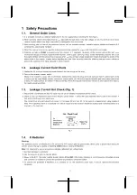
Fig. 1
1.4. X-Radiation
Warning:
The potential sources of X-Radiation in TV set are the EHT section and the picture tube. When using a picture tube test jig for
service, ensure that jig is capable of handling
29.0kV
without causing X-Radiation.
Note:
It is important to use an accurate periodically calibrated high voltage meter.
1. Set the brightness to minimum.
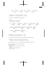
2. Use the remocon to get into Service Mode.
3. Measure the EHT. The meter reading should indicate
27.5±1.5kV
. If the meter indication is out of tolerance, immediate service
and correction is required to prevent the possibility of premature component failure.
4. To prevent the possibility X-Radiation, it is essential to use the specified picture tube, if service replacement becomes
necessary.
3
TC-21GX20P
Summary of Contents for TC-21GX20P
Page 13: ...3 Conductor Views 13 TC 21GX20P...
Page 14: ...4 Schematic Diagram 14 TC 21GX20P...
Page 15: ...15 TC 21GX20P...
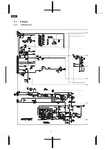
Page 16: ...4 1 A Board 4 1 1 A Board 1 5 1A 2A 3A 5A 4A 6A 7A 8A 9A 16 TC 21GX20P...
Page 17: ...4 1 2 A Board 2 5 1B 2B 4B 3B 7B 6B 5B 8B 9B 1A 2A 3A 5A 4A 6A 7A 8A 9A 17 TC 21GX20P...
Page 18: ...4 1 3 A Board 3 5 1C 2C 4C 3C 7C 6C 5C 8C 9C 1B 2B 4B 3B 7B 6B 5B 8B 9B 18 TC 21GX20P...
Page 19: ...4 1 4 A Board 4 5 1D 2D 7D 4D 3D 8D 6D 5D 9D 1C 2C 4C 3C 7C 6C 5C 8C 9C 19 TC 21GX20P...
Page 20: ...4 1 5 A Board 5 5 1D 2D 7D 4D 3D 8D 6D 5D 9D 20 TC 21GX20P...
Page 21: ...4 2 L Board 4 2 1 L Board 1 3 1A 2A 3A 4A 5A 21 TC 21GX20P...
Page 22: ...4 2 2 L Board 2 3 1B 2B 3B 4B 5B 6B 1A 2A 3A 4A 5A 22 TC 21GX20P...
Page 23: ...4 2 3 L Board 3 3 1B 2B 3B 4B 5B 6B 23 TC 21GX20P...
Page 24: ...5 Parts Locations 24 TC 21GX20P...


