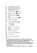
S201
: Laser ON/OFF switch in “OFF” position. /
(It turns “ON” with disc holder closed.)
S202
: Rest detector in “OFF” position. / (It turns
“ON” when optical pickup comes to
innermost periphery.)
S301
:
Select/play/pause button (
, SELECT)
S302
:
Stop/operation off button (
, STOP/OPR
OFF)
S303
:
F.Skip/Video CD next switch (
,
NEXT)
S304
:
R.Skip/Video CD previous switch (
,
PREV)
S308
: Anti-shock button (A. SHOCK)
S309
: Play mode selector (MODE) in “NORMAL”
position. / (NORMAL
PBC OFF
RESUME)
S310
: Hold switch (HOLD)
S311
: Video CD menu, select (bigger) switch
(MENU+)
S312
: Video CD menu, select (smaller) switch
(MENU-)
S313
: Return button (
, RETURN)
S314
: Video format select switch (NTSC, PAL)
VR701
: Volume control VR
VR851
: Power supply voltage adjustment VR
- The voltage values and waveforms are reference voltage of this
measured by the DC electronic voltmeter (high-impededance) and
oscilloscope on the basis of GND terminal (DC IN jack).
Accordingly, there may arise some errors in the voltagevalues and
waveforms depending on the internal impedance of the tester or
measuring unit.
- The parenthesized is the voltage for test disc (1kHz, L+R, 0dB) in
31
Summary of Contents for SL-VP48
Page 8: ...8 ...
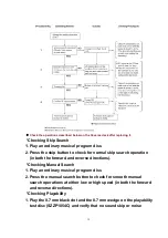
Page 9: ... Check the video P C B A side as shown below 5 1 2 Checking for the video P C B B side 9 ...
Page 13: ...13 ...
Page 14: ...14 ...
Page 15: ...5 4 Replacement for the traverse motor Follow the Step 1 Step 5 of item 5 1 1 15 ...
Page 16: ...5 5 Replacement for the optical pickup Follow the Step 1 Step 5 of item 5 1 1 16 ...
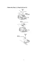
Page 17: ... Follow the Step 1 Step 5 of item 5 4 17 ...
Page 28: ...28 ...
Page 29: ...29 ...
Page 52: ...19 Packaging 52 ...

