


9
USING THIS PRODUCT AS A SAFETY EQUIP-
MENT FOR A PRESS MACHINE IN JAPAN
When using this product as a safety equipment for a press machine in
Japan, this product's installation, electrical wiring, inspection and mainte-
nance must be completed by a “qualified personnel.”
Qualified personnel refers to a press work supervisor, or other work
supervisor who has completed special training as set forth by Industrial
Safety and Health Laws, and has extensive knowledge and experience
to resolve problems and any problems related to his / her duties.
●
When used in combination with
SF4B-□-01<V2>
, this product satisfies
the “Model Examination” as set forth in the Japanese Industrial Safety
and Health Laws Provision 44-2 as indicated below.
[When using in combination with SF4B-□-01<V2>]
•
Model examination No.:
No. TA527 (
SF4B-A□-01<V2>
)
No. TA528 (
SF4B-F□-01<V2>
,
SF4B-H□-01<V2>
)
•
Conforming standards:
Standards for press machine or shear safety equipment structure
(Ministry of Labor Notice No. 102, issued September 21, 1978)
●
When using
SF4B-□-01<V2>
and this product as safety equipments for
a press machine in Japan, a pre-work inspection and periodic inspec-
tion must be carried out by the press machine work supervisor or by
the person in charge of the matters listed in Provision 134, No. 1, 2 and
4 of the Ordinance on Labor Safety and Hygiene. The press machine
work supervisor, etc., must inspect the following matters before starting
work, and must record and save the results.
Emitter of SF4B-□-01<V2>
□ Security of mounting
□
Adequacy of mounting position (safety distance and vertical position)
□ Presence of damage
□ Presence of abnormality in external wires
□ Presence of contamination on emitter
□ Security of detection state
Receiver of SF4B-□-01<V2>
□ Security of mounting
□
Adequacy of mounting position (safety distance and vertical position)
□ Presence of damage
□ Presence of abnormality in external wires
□ Presence of contamination on receiver
□ Security of detection state
Control unit SF-C13
□ External wiring
□ Indicators
□ Presence of abnormal operation with switches, etc.
□ Security of mounting
Refer to “Policy on Press Machine Safety Equipment Control” (Ministry
of Labor, Basic Publication No. 446-2, issued on July 9, 1993) for details.
●
Compatible press machines
•
When using this product as a safety equipment for a press machine
in Japan, the machine in which
SF4B-□-01<V2>
and this product are
mounted must be capable of suddenly stopping from any operation
point even during the operation cycle. Do not use
SF4B-□-01<V2>
and
this product with a machine having an irregular sudden stop.
•
Do not use this product with a power press having a full-rotation clutch.
•
When using this product as a safety equipment for a press machine in
Japan, do not use the product with a press machine that does not sat-
isfy the following specifications.
Item
Specifications
Model
Press machine having sudden stop device and restart
prevention mechanism
Pressure capacity
50,000kN or less
Sudden stop time
500ms or less
Stroke length
Within (Protective height - Die height)
Range of model height
Within bolster width
10
TROUBLESHOOTING
●
The number of times the fault indicator (yellow) blinks indicates the
type of error state, as follows.
Blinking
Description of error
Cause / Remedy
2 times
Internal relay contact is
weld
The contact was weld due to the lifetime of the
relay.
Replace this product by new one.
3 times
Reset mode error
Wiring of the terminal X1, X2 or X3 is not correct.
Check if the wiring has been correctly done.
4 times
or more
I n f l u e n c e o f n o i s e /
power supply or internal
circuit failure
Check the noise environment.
Check the wiring, power supply voltage and
voltage capacity.
●
Make sure that this product and the light curtain are connected to the
common power supply.
●
When the sensor doesn't operate properly even if the remedies de-
scribed above are taken, contact our office.
●
Interval of blinking for the fault indicator (yellow) is approx. 0.6 sec.
Check the number of times the indicator blinks for approx. 2 sec. from
the indicator “OFF” period.
WARNING
Install a RESET switch in palace where it is possible to see all over the
dangerous zone and outside of the zone.
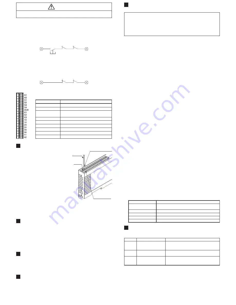
<Manual reset>
• In case of the manual reset, configure the back check circuit between X1
and X2. If it is not necessary to check KA and KB, short-circuit KA and KB.
•
Do not connect anything to X3.
•
The unit operates by the trailing operation of the external reset button.
•
Two or more units cannot be controlled by an external reset button.
Prepare the external reset button for unit by unit.
X1
RESET
KA
KB
X2
<Auto reset>
• In case of the auto reset, configure the back check circuit between X1 and X3.
If it is not necessary to check KA and KB, short-circuit between X1 and X3.
•
Do not connect anything to X2.
•
Avoid auto-reset of the system after emergency stop by using the other
control circuit. (IEC / EN 60204-1 part 9.2.5.4.2 and 10.8.3)
X1
KA
KB
X3
●
Terminal arrangement diagram
Terminal No.
Description
A1
24V DC
A2
0V
S1 to S4
Light curtain control output (OSSD) input
terminal
AUX
Semiconductor auxiliary output
X1
Reset output terminal
X2
Reset input terminal (manual)
X3
Reset input terminal (automatic)
13-14, 23-24, 33-34
Safety output (NO contact × 3)
41-42
Auxiliary output (NC contact × 1)
5
MOUNTING TERMINAL BLOCK
●
When connecting to the terminal
block, insert a solid wire or twisted
wire (lead wire) with a ferrule (sleeve)
terminal (please arrange separately)
into the hole till it stops as shown in
the figure right. The wire is locked
when it is properly inserted. However,
do not to pull the wire with excessive
force, as this can cause a cable break.
●
When connecting the twisted wire (lead wire)
without a ferrule (sleeve) terminal, insert the
wire to the innermost of the connecting hole
while pressing the release button.
●
When releasing the solid wire or the
twisted wire (lead wire), pull the wire
while pressing the release button.
Lead wire
Release
button
Solid wire or twisted
wire (lead wire) inlet
Ferrule (sleeve) terminal
(Please arrange separately)
●
The following solid wire and twisted wire (lead wire) are recommended.
Solid wire: ø0.4 to ø1.2mm (AWG 26 to 16)
Twisted wire (lead wire): 0.2 to 1.25mm
2
(AWG 24 to 16)
Standard stripped wire length: 11mm
6
SHORT-CIRCUIT PROTECTION
●
The power supply unit of this equipment adopts the electronic fuse
which do not require any replacement.
●
When the electronic fuse is operated, turn OFF the power supply, and remove
the cause of overcurrent before restarting the power supply for resetting.
●
The electronic fuse is not suitable to use in which the equipment is
operated continuously or daily. Note that operating the equipment con-
tinuously may be unable to satisfy the specifications.
7
FUNCTIONS
●
Trailing edge switching function
•
This function is to accept the input when the reset switch is pressed (con-
tact “close”) and then released (contact “open”) at the manual start setting.
An unexpected start-up due to the welded reset switch can be avoided.
8
MAINTENANCE
●
Be sure to do maintenance before use and 6 month periodic maintenance.
Refer included instruction manual of light curtain for the inspection items.
●
In case replacing this device to new this device, be sure special techni-
cian to exchange it. And do daily maintenance and periodic maintenance.
Phone: 800.894.0412 - Fax: 888.723.4773 - Web: www.clrwtr.com - Email: [email protected]


