


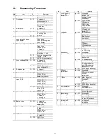


14
7 Service Fixture & Tools
7.1.
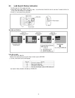
When Replacing the Main PCB
After replacing the MAIN PCB, be sure to achieve adjustment.
The adjustment instruction is available at “software download” on the “Support Information from NWBG/VDBG-PAVC” web-site in
“TSN system”, together with Maintenance software.
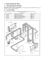
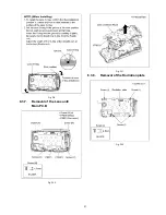
7.2.
Service Position
This Service Position is used for checking and replacing parts. Use the following Extension cables for servicing.
Table S1 Extension Cable List
No.
Parts No.
Connection
Form
1
VFK1364
FP6931 (MAIN) - CCD UNIT
14PIN 0.5 FFC
2
VFK1461
FP6971 (MAIN) - LENS UNIT
20PIN 0.5 FFC
3
VFK1388
FP6902 (MAIN) - FP4802 (FRONT)
12PIN 0.5 FFC
4
VFK1716
FP6903 (MAIN) - FP8101 (MONITOR)
25PIN 0.3 FFC
5
VFK1461
FP6905 (MAIN) - BATTERY CHATCER UNIT
20PIN 0.5 FFC
6
VFK1461
FP6961 (MAIN) - OPERATION FPC UNIT
20PIN 0.5 FFC
7
VFK1870
PS6901 (MAIN) - FP6001 (JACK)
20PIN B to B
Summary of Contents for SDR-SW20E
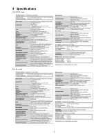
Page 9: ...9 4 Specifications For P PC PL areas For other areas ...
Page 10: ...10 ...
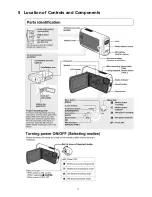
Page 11: ...11 5 Location of Controls and Components ...
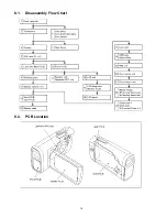
Page 16: ...16 8 1 Disassembly Flow Chart 8 2 PCB Location ...
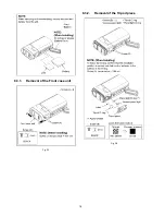
Page 18: ...18 8 3 1 Removal of the Front case unit Fig D1 8 3 2 Removal of the Tripod piece Fig D2 ...
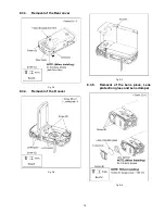
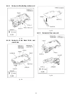
Page 20: ...20 8 3 6 Removal of the Side case L unit Fig D7 Fig D8 ...
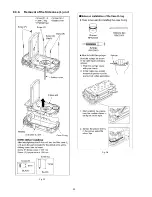
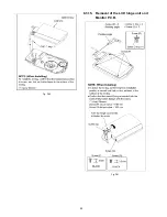
Page 24: ...24 Fig D20 8 3 15 Removal of the LCD hinge unit and Monitor P C B Fig D21 ...
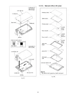
Page 25: ...25 Fig D22 8 3 16 Removal of the LCD panel Fig D23 ...
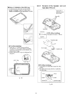
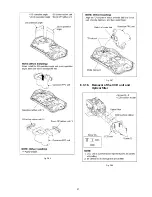
Page 26: ...26 Fig D24 8 3 17 Removal of the Speaker unit and Operation FPC unit Fig D25 ...
Page 27: ...27 Fig D26 Fig D27 8 3 18 Removal of the CCD unit and Optical filter Fig D28 ...