10
3.2.
How to Define the Model Suffix (NTSC or PAL model)
There are seven kinds of SDR-S70/S71/T70/T71/T76, regardless of the colours.
• a) SDR-S70P, SDR-S7IP, SDR-T70P
• b) SDR-S70PC, SDR-T70PC
• c) SDR-S70EB/EC/EF/EG/EP, SDR-T70EB/EC/EF/EG/EP
• d) SDR-S71GA/GN, SDR-T76GA
• e) SDR-S70EE, SDR-T70EE
• f ) SDR-S71GK
• g) SDR-S71GC/PU/PR, SDR-T71PU/PR, SDR-T76GC
What is the difference is that the "INITIAL SETTINGS" data which is stored in Flash ROM mounted on Main P.C.B.
3.2.1.
Defining methods
To define the model suffix to be serviced, refer to the nameplate which is putted on the bottom side of the Unit.
Note:
After replacing the MAIN P.C.B., be sure to achieve adjustment.
The adjustment instruction is available at "software download" on the "Support Information from NWBG/VDBG-AVC" web-site in
"TSN system", together with Maintenance software.
Summary of Contents for SDR-S70EB
Page 11: ...11 4 Specifications ...
Page 13: ...13 ...
Page 14: ...14 ...
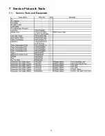
Page 18: ...18 7 Service Fixture Tools 7 1 Service Tools and Equipment ...
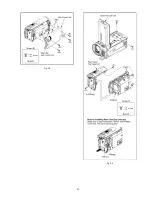
Page 21: ...21 Fig D3 Fig D4 ...
Page 24: ...24 Fig D13 Fig D14 Fig D15 Fig D16 ...
Page 25: ...25 Fig D17 Fig D18 Fig D19 Fig D20 ...
Page 26: ...26 Fig D21 Fig D22 ...
Page 28: ...28 8 4 1 How to use of CCD positioning pin RFKZ0476 ...
Page 30: ...30 9 2 2 Checking and repairing individual circuit boards How to use extension cables ...
Page 31: ...31 9 3 Location for Connectors of the Main P C B 9 3 1 Main P C B ...
Page 62: ...S 26 S7 2 LCD Section 15 17 16 18 34 19 20 21 33 B17 B26 B27 ...


