

TOP
Installation
The installation tasks are explained using 4 steps.
Step1
Make sure all items are prepared before
beginning installation.
Step2
Mount the brackets to a ceiling or wall.
Step3
Connect cables, and then attach the
camera to the mount bracket.
Step4
Open sub cover, secure camera, close
after image direction adjustment.
IMPORTANT:
Procure 4 screws (M4) to secure the
●
A
attachment plate (accessory) to a ceiling or a wall.
When mounting the camera on a concrete ceiling, use an AY plug bolt (M4) for securing.
●
(Recommended tightening torque: 1.6 N·m {1.18 lbf·ft})
Select screws according to the material of the ceiling or wall that the camera will be mount-
●
ed to. Do not use wood screws and nails.
If a ceiling board such as plaster board is too weak to support the total weight, the area
●
shall be sufficiently reinforced.
Step1 Preparations
There are 6 methods to install the camera to a ceiling or wall as described below. Prepare the
required parts for each installation method before starting the installation. The following are the
requirements for the various installation methods.
Installation method
Recommended
screw
Minimum pull-
out strength
[1]
Mounting the camera on the two-gang junction box
of the ceiling or wall using the
A
attachment plate
(accessory)
M4 screws x 4
196 N {44 lbf}/
1pc.
[2]
Directly mount the camera onto the ceiling or wall
using the attachment plate
M4 screws x 4
196 N {44 lbf}/
1pc.
[3]
Placing the camera on a table using the
J
desk-
top cover (accessory)
—
—
[4]
Mounting the camera on a standard tripod stand
(locally procured)*
1
—
—
[5]
When mounting the camera on an insufficiently
strong ceiling using the WV-Q105A (ceiling mount
brackets: approximately 150
g
{0.33 lbs})*
2
anchor bolt x 2
*3
[6]
For mounting on ceiling
*4
(mount bracket: approx. 260
g
{0.57 lbs},
camera: 400
g
{0.88 lbs})
*2
M6 or M8 screws x 4 562 N {126 lbf}/ 1 pc.
M4 x 1 (for the safety
wire)
24.5 N {5.5 lbf}
*1 Size of the camera bracket mounting hole: 1/4-20UNC camera tripod mounting hole (depth
6.0 mm (1/4 inches)).
*2 Refer to the operating instructions included with the WV-Q105A or the mounting bracket
(locally procured) for the procedure on installing the camera using the respective bracket.
*3 Make sure that the installed mount bracket can support more than 5 times of the total
weight of the camera, brackets and anchor bolt itself.
Roof space
[5]
[6]
Anchor bolt
(locally procured)
Camera
Camera
WV-Q105A
G
Cable tie (accessory)
A
Attachment
plate (accessory)
Ceiling board such
as plaster board
Fixing screw
(4 pcs.
(WV-Q105A supplied))
Safety wire (WV-Q105A supplied)
Step2 Fixing the attachment plate
Step3 Camera mounting
(1) Using a two-gang junction box
(2) Using the attachment plate (accessory)
Note:
The direction of “
●
TOP” on the
A
attachment plate (accessory) determines the upwards
direction of the image on the PC monitor.
When mounting on a ceiling, determine the direction that you want images to be dis-
●
played upwards on the PC monitor, and then mount so that the
A
attachment plate
(accessory) aligns with “ TOP” on
C
template A (accessory).
When installing on a wall, attach the
●
A
attachment plate (accessory) so that “ TOP”
faces upward.
46 mm
{1-13/16 inches}
46 mm
{1-13/16
inches}
83.5 mm
{3-9/32
inches}
83.5 mm
{3-9/32 inches}
Two-gang
junction box
TOP
TOP
TOP
Fixing M4 screws
(4 pcs., locally procured)
A
Attachment
plate (accessory)
A
Attachment plate
(accessory)
C
Template A (accessory)
Cable access hole
(ø30 mm
{ø1-3/16 inches})
Fixing M4 screws (4 pcs., locally procured)
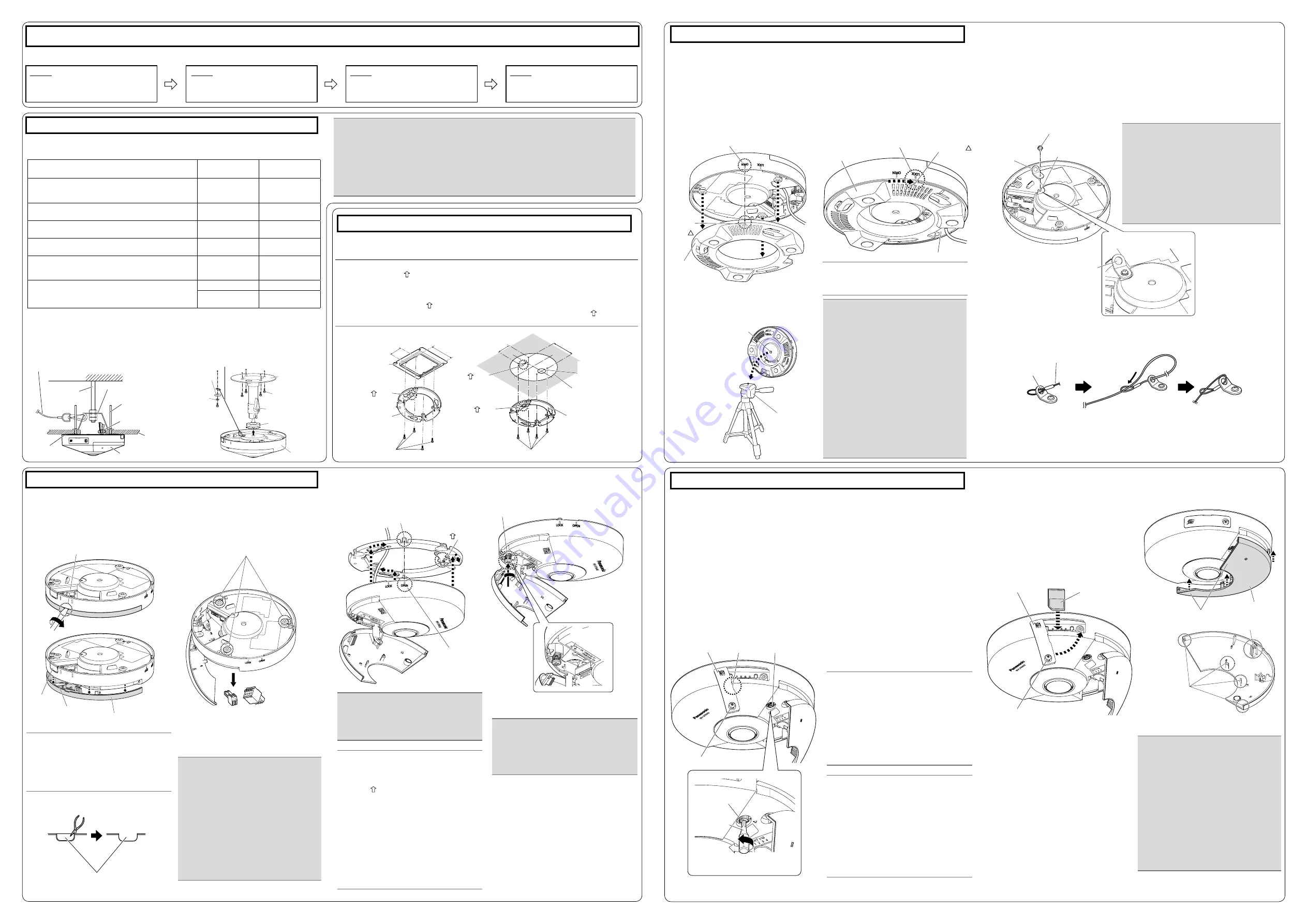
Step3 Camera mounting (continued)
Step4 Adjustment
4
Connect cables to the camera according to the
instructions in “Making connections”, and fix
the camera by inserting attachment mount-
ing screws into the holes of the
A
attachment
plate (accessory).
5
Secure the camera using the camera fixing
screw. (Recommended tightening torque:
0.78 N·m {0.58 lbf·ft})
2
Remove the
D
power cord plug (acces-
sory) and
E
external I/O terminal plug
(accessory) attached to the camera.
3
Check the position of the 3 attachment
mounting screws on the bottom side of the
camera.
1
Connect the cables to the camera.
2
Align the attachment position marker on
the desktop cover with “OPEN” on the side
of the camera, and engage the camera
attachment fixing screws in the rear of the
camera with the camera mounting holes of
the desktop cover.
1
Loosen the SD memory card slot cover fix-
ing screw on the side of the camera using
the
B
bit (accessory), then insert the tip of
a small slotted head screwdriver, etc. into
the notched area to remove the SD memory
card slot cover.
2
Remove the cover film from the lens sur-
face.
3
Turn on the camera. The LINK indicator
inside the SD memory card slot cover lights.
Make sure that the ACT indicator is blinking.
(Refer to the descriptions in “Major operat-
ing controls” for more information about the
indicators.)
* After turning on the camera, there may be
a sound produced from the lens for several
seconds. This is not a malfunction.
6
Insert an SD memory card into the slot, if
necessary.
Insert the SD memory card with its label
●
facing down.
7
Close the SD memory card slot cover, and
tighten the SD memory slot cover slot cover
fixing screw to secure the cover.
(Recommended tightening torque: 0.39 N·m
{0.29 lbf·ft})
8
Return the sub cover to its original position
and secure it.
4
Perform camera settings while referring to
the included “Configure the settings of the
camera” (leaflet), and check if camera im-
ages are displayed on the PC monitor.
5
Align the upwards direction of the image
while rotating the image rotation gear and
checking the image on the PC monitor.
Rotate the image rotation gear using the bit
(accessory), and align the upwards direction of
the image as necessary.
Rotating the image rotation gear clockwise
also rotates the PC image clockwise. Rotating
the image rotation gear counterclockwise also
rotates the PC image counterclockwise.
Adjustable range of the PC image
-45° to +45°
The default position of the image rotation
●
gear is 0°.
Note:
When Double Panorama or Panorama
●
is selected for the Image capture
mode, you can rotate the image at 90°
intervals by using preset position set-
tings. To make further fine adjustments
to the image angle, adjust the image
rotation gear. Refer to 11.1 and 11.5.4
of the Operating Instructions for more
information.
Note:
Take care of the following points when
using monitor out.
Select “9M Fisheye” or “4M Fisheye”
●
for “Image capture mode”.
Locally procure the ø3.5 mm monaural
●
mini plug
⇔
RCA pin jack conversion
cable.
Select the [Setup]→[Basic] tab, and
●
then select On (NTSC) or On (PAL) for
[Monitor out].
4
When mounting on a standard tripod stand
(locally procured), attach the desktop cover
to the camera before mounting on the
standard tripod stand.
1
Secure the
H
safety wire lug (accessory) to the camera with the
I
wire lug fixing screw
(accessory). Secure the safety wire lug as shown in the following illustrations.
2
Attach the safety wire (accessory) to the wire mounting hole of the safety wire lug. (The cam-
era is not shown in the following illustrations.)
3
Rotate the desktop cover in the direction of
the arrow to secure the camera. Process
the wiring by passing the cables through the
cable access hole in the desktop cover.
Make sure that the attachment position
marker on the desktop cover will be set to
the “LOCK” position.
■
When using the attachment plate
1
Insert a thin slotted head screwdriver, etc.
into the sub cover groove of the camera,
rotate the slotted head screwdriver as
shown in the illustration below, and then
remove the sub cover.
■
When installing the camera on a desktop or standard tripod stand (locally procured)
When installing the camera on a desktop or standard tripod stand (locally procured), attach the
J
desktop cover (accessory) to the camera. The
A
attachment plate (accessory) is not used
when installing the camera on a desktop or standard tripod stand (locally procured).
■
When mounting the camera on the WV-Q105A or the mounting bracket (locally pro-
cured)
Refer to the operating instructions included with the WV-Q105A or the mounting bracket (locally
procured) for the procedure on installing the camera using the respective bracket. The following
are descriptions of
K
safety wire (accessory) attachment when mounting the camera on the
mounting bracket (locally procured).
Sub cover groove
Protruding part
Image rotation gear
B
Bit
(accessory)
OPEN mark
Camera fixing screw
Attachment mounting screws
Side cable
access hole
Sub cover sheet
Side cable access hole
Sub cover
Camera fixing
screw
TOP
Note:
When installing the camera directly on
●
the ceiling or wall with cables
exposed, cut out a portion of the
enclosure to open a cable access
hole.
Note:
After the cables have been connected
●
to the camera, align the direction of
the Panasonic logo on the camera
with “ TOP” of the
A
attachment
plate (accessory). Align the OPEN
mark on the side of the camera with
the protruding part of the attachment
plate, insert 3 attachment mounting
screws into the attachment plate,
rotate the camera approximately 15 °,
and move the LOCK mark to the pro-
truding part of the attachment plate to
temporarily secure the camera.
After connecting the cables, use a
●
G
cable tie (accessory) for wiring pro-
cessing as necessary.
* Wiring and the sub cover are not shown in
some illustrations from this point.
IMPORTANT:
Because the sub cover is attached to
●
the camera with the sub cover sheet,
do not pull the sub cover with exces-
sive force. Failure to observe this may
damage the sub cover.
To prevent injury and protect cables,
●
smooth opened cable access holes of
the enclosure with a file or other tool.
To prevent filings or other substances
●
entering inside the camera, open the
sub cover when using a file or other
tool to smooth the cable access
holes.
IMPORTANT:
Because the bottom side of the cam-
●
era may become hot, make sure to
use the camera with the
J
desktop
cover (accessory) attached.
The specified operating temperatures
●
for the camera are -10 °C to +40 °C
{14 °F to 104 °F} when it is installed
on a desktop or standard tripod stand.
Use a standard tripod stand with a tri-
●
pod head of ø75 mm or less.
When mounting on a standard tripod
●
stand, take care because knocking
over the tripod or damaged screws
may cause the camera to fall.
Use a standard tripod stand that is
●
capable of supporting a load more
than the weight of the camera (440
g
{0.97 lbs}).
IMPORTANT:
Make sure to attach the safety wire lug so
●
that the wire mounting hole faces outward.
When it is attached facing inward, it may
touch the camera mount bracket.
Use the
●
I
wire lug fixing screw (accesso-
ry) to attach the
H
safety wire lug (acces-
sory). When using different length screws,
it may damage the camera or cause the
camera to fall.
(Recommended tightening torque:
0.39 N·m {0.29 lbf·ft})
IMPORTANT:
Disconnect either the 12 V DC power
●
source or PoE power source to pre-
vent power from being supplied while
mounting the camera.
IMPORTANT:
Be sure to tighten the camera fixing
●
screw. Failure to observe this may cause
camera trouble due to camera falling.
(Recommended tightening torque:
0.78 N·m {0.58 lbf·ft})
IMPORTANT:
Ensure that the SD memory card slot
●
cover's fixing screw is firmly secured.
Make sure that the sub cover is
●
securely fixed.
After the installation is completed,
●
clean the lens surface with a soft
cloth, etc.
After the installation is complete, if the
●
image is out of focus, turn off the
camera, and then turn it on again. If
the image is still out of focus, select
the [Image/Position] tab from
[Setup]→[Image/Audio], and then re-
adjust the back focus from [Setup>>]
of [Back focus].
OPEN
J
Desktop
cover
(accessory)
J
Desktop cover
(accessory)
Cable access hole
I
Wire lug fixing screw (accessory)
Safety wire lug
attachment example
LOCK
Attachment
position
marker
Attachment
position marker
H
Safety wire lug
(accessory)
Wire lug fixing
screw hole
Wire mounting hole
Safety wire
(accessory)
Wire mounting hole
Pass the ring part of the safety
wire (accessory) through the wire
mounting hole.
Pass the other end of the safety
wire through the ring part of the
safety wire.
Notched area
SD memory card
slot cover
SD memory card
slot cover
SD memory card slot cover fixing screw
SD memory card
Sub cover interior
Sub cover exterior
Sub cover exterior hook
Sub cover
interior hook
Image rotation gear
SD memory card slot cover fixing
screw
* Part of the sub cover is not shown.
* Part of the sub cover is not shown.
To remove the SD memory card, hold down
●
the SD ON/OFF button for about 2 seconds.
When the flashing SD MOUNT indicator
goes out, you can remove the SD memory
card.
After the SD memory card has been
●
replaced, press the SD ON/OFF button, and
make sure the SD MOUNT indicator is con-
tinually lit.
If you do not press the SD ON/OFF button
●
after replacing the SD memory card, the SD
MOUNT indicator is continually lit approxi-
mately 5 minutes later.
* When removing the camera, perform
removal by following the installation
procedure in the reverse order.
Secure the sub cover exterior hook first,
●
then push in the interior hook.
Locking arm
Platform
K
Safety wire (accessory)
Camera
mount bracket
Screw
(M6 or M8 x 4 pcs.
(locally procured))
Tripod
(locally procured)
Camera mount bracket
fixing screw hole
(screw: 1/4-20 UNC
standard, depth 6 mm
(1/4 inches))
Note:
The screw hole in the
J
desktop cover
(accessory) is not used.
L
Washer
(accessory)
M
Spring washer
(accessory)


