background image

22

As of November 2009

Product Service

1. Damage requiring service

—The unit should be 

serviced by qualified service personnel if:

(a) The AC power supply cord or AC adaptor 

has been damaged; or

(b) Objects or liquids have gotten into the unit; or
(c) The unit has been exposed to rain; or
(d) The unit does not operate normally or 

exhibits a marked change in performance; or

(e) The unit has been dropped or the cabinet 

damaged.

2. Servicing

—Do not attempt to service the unit 

beyond that described in these operating 
instructions. Refer all other servicing to 
authorized servicing personnel.

3. Replacement parts

—When parts need 

replacing ensure the servicer uses parts 
specified by the manufacturer or parts that have 
the same characteristics as the original parts. 
Unauthorized substitutes may result in fire, 
electric shock, or other hazards.

4. Safety check

—After repairs or service, ask the 

servicer to perform safety checks to confirm that 
the unit is in proper working condition.

The servicer will require all components to service 
your system.
Therefore, should service ever be necessary, be 
sure to bring the entire system.

For product information or assistance with product 
operation:

In the U.S.A. and Puerto Rico, refer to “Customer 
Services Directory (United States and Puerto Rico)” 
above.

In Canada, contact the Panasonic Canada Inc. 
Customer Care Centre at 1-800-561-5505, or visit 
the website (www.panasonic.ca), or an authorized 
Servicentre closest to you.

Customer Services Directory (United States and Puerto Rico)

Obtain Product Information and Operating Assistance; locate your nearest Dealer or Service 
Center; purchase Parts and Accessories; or make Customer Service and Literature requests by 
visiting our Web Site at:
http://www.panasonic.com/help
or, contact us via the web at:
http://www.panasonic.com/contactinfo

You may also contact us directly at:
1-800-211-PANA (7262)
Monday-Friday 9am-9pm, 
Saturday-Sunday 10am-7pm EST

For hearing or speech impaired TTY users, TTY: 1-877-833-8855 

Accessory Purchases (United States and Puerto Rico)

Purchase Parts, Accessories and Instruction Books online for all Panasonic Products by visiting our Web 
Site at: 
http://www.pstc.panasonic.com
Or, send your request by E-mail to: 
[email protected]
You may also contact us directly at:
1-800-332-5368 (Phone)  1-800-237-9080 (Fax Only)
(Monday-Friday 9am-9pm EST)
Panasonic Service and Technology Company
20421 84th Avenue South, Kent, WA 98032
(We accept Visa, MasterCard, Discover Card, American Express, and Personal Checks)

For hearing or speech impaired TTY users, TTY: 1-866-605-1277 

Product information

SCHTB500PP_RQTX1179-Y.book  Page 22  Friday, June 18, 2010  10:07 AM

Summary of Contents for SCHTB500 - HOME THEATER AUDIO SYSTEM

Page 1: ...iffer from your unit Included Installation Instructions The installation should be done by a qualified installation specialist Before commencing work carefully read these installation instructions and the operating instructions to ensure that installation is performed correctly Please keep these instructions You may need them when maintaining or moving this unit If you have any questions contact F...

Page 2: ...electrolyte should come into contact with your eyes never rub the eyes Rinse eyes thoroughly with water and then consult a doctor Warning Risk of fire explosion and burns Do not disassemble heat above 60 oC 140 oF or incinerate The unit should be installed near an accessible AC power outlet with the power cord connected directly to it To completely disconnect power from the unit unplug the power c...

Page 3: ...the apparatus has been damaged in any way such as power supply cord or plug is damaged liquid has been spilled or objects have fallen into the apparatus the apparatus has been exposed to rain or moisture does not operate normally or has been dropped Licenses The model number and serial number of this product can be found on either the back or the bottom of the unit Please note them in the space pr...

Page 4: ... cord connection 13 Active subwoofer wireless connection 13 Using this unit 14 Audio effects 15 The various audio effects 15 Changing the audio effects 15 Linked operations with the TV VIERA LinkTM HDAVI ControlTM 16 Specifications 17 Audio information 18 Troubleshooting 18 Remote control code 20 Limited Warranty ONLY FOR U S A AND PUERTO RICO 21 Product Service 22 Limited Warranty ONLY FOR CANADA...

Page 5: ...ade your purchase Unit care Clean this unit with a soft dry cloth Never use alcohol paint thinner or benzine to clean this unit Before using chemically treated cloth carefully read the instructions that came with the cloth To dispose or transfer this unit If you discard this unit either by disposal or transfer please follow the procedure to return all the settings to the factory presets to delete ...

Page 6: ...tor E Audio format indicator 5 Remote control signal sensor Remote control operation range Distance Within approx 7 m 23 ft Angle Approx 10o up and 30o down 30o left and right 6 Active subwoofer on off button 7 WIRELESS LINK indicator 1 Digital transmitter dock 12 2 AC IN terminal 13 3 Ir SYSTEM terminal Only for use with the optional IR Blaster 9 4 HDMI AV OUT terminal 11 5 OPTICAL DIGITAL AUDIO ...

Page 7: ... To replace a button type battery 1 While pressing the stopper B pull out the battery holder 2 Set the button type battery with its i mark facing upward and then put the battery holder back in place When the button type battery runs down replace it with a new battery part number CR2025 The battery should normally last about 1 year however this depends on how frequently the unit is used Keep the bu...

Page 8: ...ife if you play sound at high levels over extended periods Placing this unit too close to the floor walls and corners can result in excessive bass Cover walls and windows with thick curtains Do not use the active subwoofer or this unit in a metal cabinet or bookshelf Caution This unit the supplied wall mount brackets and the active subwoofer are to be used only as indicated in these operating inst...

Page 9: ...ctive subwoofer within approximately 10 m 33 ft of this unit and in a horizontal position with the top panel faced upward To allow for proper ventilation and to maintain good airflow around the active subwoofer position it with at least 5 cm 2z of space on all sides Do not use the active subwoofer or this unit in a metal cabinet or bookshelf The Active subwoofer To avoid interference maintain the ...

Page 10: ...cm 26 98 lbf ft Repeat the steps above when installing the second wall mount bracket 3 Thread a cord not supplied through each wall mount bracket Make sure to use a cord which is capable of supporting over 20 kg 44 1 lbs A Rear of this unit B Fall prevention cord not supplied 4 After all the necessary connections are finished 11 Place the unit in the desired position and attach each cord onto the ...

Page 11: ...tput to this unit connect using the optical digital audio cable right Basic connection with an optical digital audio cable compatible TV A HDMI cable not supplied B Optical digital audio cable not supplied When connected to an ARC compatible TV set TV Audio to ARC Off to output the audio signal from the optical digital audio cable 20 TV Audio Connection to a TV HDMI The HDMI connection supports VI...

Page 12: ...ating instructions of the connected HDMI compatible device for the necessary setting to output the video and audio signals A Digital transmitter supplied Insert fully until you hear a click Connection from an HDMI compatible device AV OUT HDMI AV IN A HDMI cable not supplied E g Blu ray Disc Player Digital transmitter connection Do not insert or remove while this unit is on DIGITAL TRANSMITTER DIG...

Page 13: ...connections are complete Press POWER C I B Í on the active subwoofer A Unit on off button POWER C I B Í Use this button to turn the unit on and off C I The active subwoofer is on B Í The active subwoofer is off B WIRELESS LINK indicator Red The active subwoofer is on and the wireless link is deactivated Green The active subwoofer is on and the wireless link is activated AC power supply cord connec...

Page 14: ... device connected to the HDMI AV IN terminal will continue to output audio or video to the TV A The selected audio source is indicated Green When the TV is the audio source Red When the device connected to the HDMI AV IN terminal is the audio source Press i VOL j to adjust the volume of the speakers Press i SUBWOOFER j to adjust the subwoofer level B The indicators blink from left to right i or fr...

Page 15: ... Clear mode Dialog B Sound Effect C Dolby Virtual Speaker VS On The indicator lights Off The indicator blinks 3 While the indicator is lit or blinking press the same button again to change the setting When turning the audio effects on or off there might be a slight pause in the audio This is normal Dolby Virtual Speaker VS is also turned on when Sound Effect is turned on It will remain on even aft...

Page 16: ...vidual manuals for other manufacturers equipment supporting VIERA Link function You can select whether audio output is from this unit or the TV speakers by using the TV menu settings Home theater This unit s speakers are active When this unit is in standby mode changing the TV speakers to this unit in the TV menu will automatically turn this unit on and select TV as the source You can control the ...

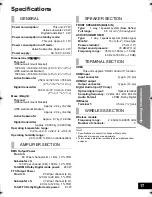
Page 17: ...FRONT SPEAKERS BUILT IN Type 1 way 1 speaker system Bass Reflex Full range 6 5 cm 21 2q Cone typek2 ACTIVE SUBWOOFER Type 1 way 1 speaker system Kelton type Woofer 16 cm 61 2q Cone type Passive radiator 25 cm 10q Output sound pressure 78 dB W 1 m Frequency range 35 Hz to 180 Hz s16 dB 40 Hz to 160 Hz s10 dB HDMI This unit supports HDAVI Control 5 function HDMI input Input connector Type A 19 pin H...

Page 18: ... necessary to set the code of the remote control again after changing the battery of the remote control 20 This unit does not operate correctly If the HDMI cable is connected to the wrong terminal HDMI AV IN or HDMI AV OUT this unit will not operate correctly Turn this unit off disconnect the AC power supply cord and reconnect the HDMI cable s 11 When operating the connected device this unit react...

Page 19: ...y the audio input terminal 20 TV Audio Audio is output from the TV speakers and not this unit s When connected to a VIERA Link HDAVI Control compatible TV change the audio output settings to this unit 16 Both main and secondary audio are output simultaneously Change the digital audio output setting on the TV or connected device and then select the desired audio channel For details refer to the ope...

Page 20: ...io to ARC Off only when using an optical digital audio cable with an ARC compatible TV 19 Sound Press and hold INPUT SELECTOR on this unit and TV on the remote control for more than 2 sec Set TV Audio to Auto Press and hold INPUT SELECTOR on this unit and CLEAR MODE DIALOG on the remote control for more than 2 sec When other Panasonic products respond to this unit s remote control change the remot...

Page 21: ...ted Warranty Limits And Exclusions This warranty ONLY COVERS failures due to defects in materials or workmanship and DOES NOT COVER normal wear and tear or cosmetic damage The warranty ALSO DOES NOT COVER damages which occurred in shipment or failures which are caused by products not supplied by the warrantor or failures which result from accidents misuse abuse neglect mishandling misapplication a...

Page 22: ...U S A and Puerto Rico refer to Customer Services Directory United States and Puerto Rico above In Canada contact the Panasonic Canada Inc Customer Care Centre at 1 800 561 5505 or visit the website www panasonic ca or an authorized Servicentre closest to you Customer Services Directory United States and Puerto Rico Obtain Product Information and Operating Assistance locate your nearest Dealer or S...

Page 23: ...FOR A PARTICULAR PURPOSE IN NO EVENT WILL PANASONIC CANADA INC BE LIABLE FOR ANY SPECIAL INDIRECT OR CONSEQUENTIAL DAMAGES In certain instances some jurisdictions do not allow the exclusion or limitation of incidental or consequential damages or the exclusion of implied warranties so the above limitations and exclusions may not be applicable WARRANTY SERVICE FOR PRODUCT OPERATION ASSISTANCE please...

Page 24: ...it in any other way Otherwise the unit may drop and become damaged and personal injury may result Do not install at a location other than a vertical wall Otherwise the unit may drop and become damaged and personal injury may result CAUTION Do not install at any locations subject to humidity dust smoke steam or heat or under an air conditioner where water may drip onto the unit This may have an adv...

Page 25: ...rtical wall To ensure correct unit performance and prevent trouble do not install at any of the following locations jNear sprinklers or fire smoke detectors jWhere there is a risk of exposure to vibration or impact jNear high voltage wires or dynamic power supplies jNear sources of magnetism heat water vapour or soot jLocations exposed to air blown from heating equipment jWhere droplets of condens...

Page 26: ...y other method than specified to install Preparation To prevent damage or scratches lay down a soft cloth and perform the assembly on it Keep the screws out of reach of children to prevent swallowing Do not hold this unit in one hand to avoid injury by dropping this unit when carrying 1 On the rear of the unit Place the wall mount bracket by aligning the holes in the wall mount bracket with the pr...

Page 27: ...e above the unit and 100 mm 315 16q on either side of the unit If not it will not be possible to attach the unit to the wall Be sure that there is enough space above the unit and that the screw hole positions are level with each other before drilling into the wall Be sure to use a spirit level to ensure that both screwing positions are horizontal to each other 5 Checking the strength of the instal...

Page 28: ... Drive 2 screws not supplied into the screwing positions identified in step 4 A At least 30 mm 13 16q B 4 0 mm 5 32q C 7 8 mm to 9 4 mm 5 16q to 13 32q D Wall E 5 0 mm to 6 0 mm 3 16q to 1 4q Take care when fixing this unit to the wall Always ensure that there are no electrical cables or pipes in the wall before hanging this unit Keep the screws out of reach of children to prevent swallowing Be su...

Page 29: ...ear of this unit B Lock pin supplied C Screw not supplied Be sure to attach both lock pins correctly 11 Attach the cord to a wall with a screw not supplied Keep the screws out of reach of children to prevent swallowing Check the strength of the installation location The position in the wall where the screw is to be attached should be capable of supporting over 20 kg 44 1 lbs If the strength at any...

Page 30: ...io TV technician for help FCC caution To maintain compliance with FCC regulations shielded interface cables must be used with this equipment Operation with non approved equipment or unshielded cables may result in interference to radio and TV reception Any changes or modifications not approved by the party responsible for compliance could void the user s authority to operate this equipment This de...

Page 31: ...r consultation ultérieure Les illustrations peuvent être différentes de l apparence réelle de l appareil Instructions d installation à l intérieur L installation ne devrait être effectuée que par un technicien qualifié Avant de commencer lire attentivement les instructions d installation et le manuel d utilisation afin de s assurer que l installation est effectuée correctement Conserver ces instru...

Page 32: ...es objets métalliques Évitez de recharger démonter remodeler chauffer ou jeter au feu Gardez hors de la portée des enfants Si de l électrolyte entre en contact avec vos mains ou vos vêtements lavez les avec beaucoup d eau Si de l électrolyte pénètre dans vos yeux ne les frottez pas Rincez vous les yeux avec beaucoup d eau puis consultez un médecin Avertissement Risque d incendie d explosion et de ...

Page 33: ...gé liquide renversé ou objet tombé dans l appareil exposition à la pluie ou à une humidité excessive mauvais fonctionnement ou chute de l appareil Licences Il est recommandé de noter dans l espace prévu ci dessous le numéro de modèle et le numéro de série inscrits à l arrière ou sous le fond de l appareil et de conserver ce manuel pour référence ultérieure NUMÉRO DE MODÈLE __________________ NUMÉR...

Page 34: ...nt de l émetteur numérique 12 Raccordement du cordon d alimentation 13 Raccordement sans fil de l enceinte d extrêmes graves avec amplificateur 13 Utilisation de l appareil 14 Effets audio 15 Divers effets audio 15 Changement des effets audio 15 Opérations liées avec le téléviseur VIERA LinkTM HDAVI ControlTM 16 Spécifications 17 Informations audio 18 Guide de dépannage 18 Code de télécommande 20 ...

Page 35: ...our peinture ni de benzène pour nettoyer l appareil Avant d utiliser un chiffon traité chimiquement lire attentivement les directives sur l emballage du chiffon Mise au rebut ou transfert de l appareil Avant de mettre l appareil au rebut ou d en transférer la propriété suivre la procédure pour réinitialiser tous les paramétrages de manière à supprimer toutes les informations conservées en mémoire ...

Page 36: ...écommande Portée utile de la télécommande Portée À l intérieur d environ 7 m 23 pi Angle Environ 10o vers le haut 30o vers le bas et 30o vers la gauche ou la droite 6 Touche de mise en hors marche de l enceinte d extrêmes graves 7 Voyant de liaison sans fil WIRELESS LINK 1 Station d accueil de l émetteur numérique 12 2 Prise d alimentation c a 13 3 Prise Ir SYSTEM Seulement pour une utilisation av...

Page 37: ...a pile bouton 1 Tout en appuyant sur la butée B retirez le support de pile 2 Placez la pile bouton avec sa marque i vers le haut et remettez en place le support de pile Lorsque la pile bouton est épuisée remplacez la par une pile neuve numéro de pièce CR2025 Normalement la pile devrait durer environ 1 an mais cela dépend de la fréquence d utilisation de l appareil Conservez la pile de type bouton ...

Page 38: ...e élevé peut endommager les haut parleurs et réduire leur durée de vie Le fait de placer cet appareil trop proche des murs planchers ou coins peut causer des graves trop prononcés Couvrir les murs et les fenêtres avec des rideaux épais Ne pas placer l enceinte d extrêmes graves ni l appareil dans un meuble ou une bibliothèque en métal Avis L appareil les supports d installation murale et l enceint...

Page 39: ...lificateur à l horizontale le panneau du dessus vers le haut à l intérieur d un rayon d environ 10 m 33 pi de l appareil principal Pour permettre une ventilation adéquate et maintenir une bonne circulation d air autour de l enceinte d extrêmes graves assurer un dégagement d au moins 5 cm 2 po sur tous les côtés Ne pas placer l enceinte d extrêmes graves ni l appareil dans un meuble ou une biblioth...

Page 40: ... 80 N0cm 17 98 lbf pi à 120 N0cm 26 98 lbf pi Répéter les étapes ci dessus lors de l installation du second support 3 Passer un câble non fourni dans la fente de chaque support d installation murale S assurer d utiliser un câble capable de supporter une charge de plus de 20 kg 44 1 lb A Arrière de l appareil B Câble de protection contre la chute non fourni 4 Une fois tous les raccordements effectu...

Page 41: ...tique numérique à droite Connexion de base à un téléviseur compatible avec câble audio optique numérique A Câble HDMI non fourni B Câble audio optique numérique non fourni Lors d une connexion à un téléviseur à la norme ARC régler Entrée audio télé sur ARC désactivé pour que le rendu audio se fasse à partir du câble audio optique numérique 20 Entrée audio télé Raccordement à un téléviseur HDMI La ...

Page 42: ...de l appareil compatible à HDMI pour en savoir plus sur les réglages requis pour la sortie des signaux vidéo et audio A Émetteur numérique fourni Introduire à fond jusqu à ce qu un clic se fasse entendre Raccordement à partir d un appareil à la norme HDMI AV OUT HDMI AV IN A Câble HDMI non fourni Ex Lecteur Blu ray Raccordement de l émetteur numérique Ne pas insérer ou retirer lorsque la chaîne ci...

Page 43: ... enceinte d extrêmes graves A Touche de mise en hors marche POWER C I B Í Utiliser cette touche pour mettre l appareil en marche ou hors marche C I L enceinte d extrêmes graves avec amplificateur est en marche B Í L enceinte d extrêmes graves avec amplificateur est hors marche B Voyant de liason sans fil WIRELESS LINK Rouge L enceinte d extrêmes graves avec amplificateur est en marche et la liaiso...

Page 44: ...rise d entrée HDMI AV IN continuera de livrer le signal audio ou vidéo au téléviseur A La source audio sélectionnée est indiquée Vert Lorsque le téléviseur est la source audio Rouge Lorsque l appareil raccordé à la prise HDMI AV IN est la source audio Appuyer sur i VOL j pour ajuster le volume des haut parleurs Appuyer sur i SUBWOOFER j pour ajuster le niveau de sortie des extrêmes graves B Les in...

Page 45: ...C Haut parleur virtuel Dolby VS Activé L indicateur s illumine Désactivé L indicateur clignote 3 Lorsque l indicateur est allumé ou clignote appuyer de nouveau sur la même touche afin de modifier le paramétrage Une légère interruption du son pourrait survenir lors de l activation ou de la désactivation de ces effets ceci est normal Le haut parleur virtuel Dolby VS est également mis en marche lorsq...

Page 46: ...u des paramétrages du téléviseur quels haut parleurs sont en circuit ceux du téléviseur ou ceux de cet appareil Cinéma maison Les haut parleurs de la chaîne cinéma maison sont activés Lorsque cet appareil est dans le mode veille activer les haut parleurs de ce dernier à partir du menu des paramétrages du téléviseur a pour effet de mettre automatiquement l appareil en marche et de sélectionner TV e...

Page 47: ...T INTÉGRÉS Type 1 voie 1 haut parleur évent réflex Pleine gamme 6 5 cm 21 2 po de type cônek2 ENCEINTE D EXTRÊMES GRAVES AVEC AMPLIFICATEUR Type 1 voie 1 haut parleur de type Kelton Graves 16 cm 61 2 po de type cône Radiateur passif 25 cm 10 po Pression sonore de sortie 78 dB W 1 m Plage de fréquences 35 Hz à 180 Hz s16 dB 40 Hz à 160 Hz s10 dB HDMI Cet appareil prend en charge la fonction HDAVI C...

Page 48: ...a télécommande 20 Cet appareil ne fonctionne pas adéquatement Si le câble HDMI est connecté à la mauvaise prise HDMI AV IN ou HDMI AV OUT l appareil ne fonctionnera pas de manière adéquate Le mettre hors marche débrancher le cordon d alimentation et reconnecter le s câble s HDMI 11 Lors du pilotage d un appareil raccordé cet appareil réagit de manière inadéquate Les commandes de la fonction HDAVI ...

Page 49: ... audio est livré par les haut parleurs du téléviseur et non par ceux de cet appareil Lors du raccordement à un téléviseur compatible avec VIERA Link HDAVI Control commuter les réglages du rendu audio sur cet appareil 16 Le rendu sonore principal et secondaire sont émis simultanément Modifier le réglage de sortie audio numérique sur le téléviseur ou sur l appareil connecté puis sélectionner le cana...

Page 50: ...r ARC désactivé seulement lors de l utilisation d un câble audio optique numérique avec un téléviseur à la norme ARC 19 Rendu sonore Appuyer et tenir enfoncées pendant plus de 2 s les touches INPUT SELECTOR de cet appareil et TV de la télécommande Régler Entrée audio télé sur Auto Appuyer et tenir enfoncées pendant plus de 2 s les touches INPUT SELECTOR de cet appareil et CLEAR MODE DIALOG de la t...

Page 51: ...centre de service Panasonic agréé 3 Pièces de rechange S assurer que le technicien utilise des pièces de rechange recommandées par le fabricant ou dont les caractéristiques sont les mêmes L utilisation de pièces de rechange non autorisées peut causer un incendie des chocs électriques ou d autres dangers 4 Vérification de sécurité Demander au technicien qui a réparé l appareil de soumettre ce derni...

Page 52: ... Certaines juridictions ne reconnaissent pas les exclusions ou limitations de dommages indirects ou consécutifs ou les exclusions de garanties implicites Dans de tels cas les limitations stipulées ci dessus peuvent ne pas être applicables RÉPARATION SOUS GARANTIE Pour de l aide sur le fonctionnement de l appareil veuillez contacter notre service à la clientèle au No de téléphone 905 624 5505 Ligne...

Page 53: ...l installer d aucune autre manière Autrement l appareil pourrait tomber et être endommagé et entraîner un risque de blessure Ne pas installer sur une surface autre qu un mur vertical Autrement l appareil pourrait tomber et être endommagé et entraîner un risque de blessure ATTENTION Ne pas installer dans des endroits exposés à l humidité la poussière la fumée la vapeur ou la chaleur ou sous un clim...

Page 54: ...une surface autre qu un mur vertical Pour un rendement optimal et prévenir tout problème ne pas installer l appareil jprès d un gicleur ou d un détecteur d incendie de fumée jdans un endroit où l appareil pourrait subir de la vibration ou des chocs jprès d une ligne à haute tension ou d une source d alimentation électrique jprès d un champ magnétique d une source de chaleur de vapeur de suies jdan...

Page 55: ...utiliser une méthode d installation autre que celle spécifiée Préparatifs Afin de prévenir des rayures ou tout autre dommage déposer un chiffon doux sur la surface où se fera l assemblage En raison du risque d ingestion garder les vis hors de portée des enfants Ne pas tenir l appareil avec une seule main pour éviter des blessures dans le cas où ce dernier tomberait pendant le transport 1 À l arriè...

Page 56: ... 32 po au dessus de ce dernier et 100 mm 315 16 po sur le côté Autrement il ne sera pas possible de fixer l appareil au mur S assurer de laisser suffisamment d espace au dessus de l appareil et que l emplacement des vis sur le mur sont au même niveau avant de percer les trous Utiliser une règle à niveau afin de s assurer que les deux endroits de fixation sont à l horizontale 5 Vérification de la s...

Page 57: ...e verrouillage au delà de ce point 8 Placer deux vis non fournies dans la position de fixation indiquée à l étape 4 A Au moins 30 mm 13 16 po B 4 0 mm 5 32 po C 7 8 mm à 9 4 mm 5 16 po à 13 32 po D Mur E 5 0 mm à 6 0 mm 3 16 po à 1 4 po Faire preuve de prudence lors de l installation murale Toujours s assurer qu il n y a ni câble électrique ni tuyau dans le mur avant d accrocher cet appareil En ra...

Page 58: ...de l appareil B Tiges de verrouillage fournies C Vis non fournies S assurer de fixer les deux tiges de verrouillage correctement 11 Fixer le câble à un mur au moyen d une vis non fournie En raison du risque d ingestion garder les vis hors de portée des enfants Vérifier la solidité de l emplacement d installation L endroit du mur où sera fixée la vis doit pouvoir supporter une charge de plus de 20 ...

Page 59: ...Instructions d installation 29 ...

Page 60: ...2Y F0510AC2006 Si ce symbole apparaît Information sur la mise au rebut dans les pays n appartenant pas à l Union européenne Ce symbole est uniquement valide dans l Union européenne Si vous désirez mettre ce produit au rebut contactez l administration locale ou le revendeur et informez vous de la bonne façon de procéder ...

Reviews: