46
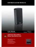
Step 8 :
Remove the Digital Transmitter Module P.C.B. as
shown.
Caution: During assembling, ensure that the Digital Trans-
mitter Module P.C.B. is fully inserted into the Wireless
Adapter P.C.B. as direction with Shield Plate is facing to
Ground Spring.
11.4.10. Disassembly of Power Button
P.C.B.
• Refer to “Disassembly of Top Cabinet”.
• Refer to “Disassembly of Front Panel Block”.
Step 1 :
Remove 1 screw.
Step 2 :
Remove the Stopper P.C.B. through the 2P Cable Wire
as shown.
Caution: During assembling, ensure that the Stopper
P.C.B. is seated properly onto the guides of the Front Panel
Block.
Summary of Contents for SB-HTB550GK
Page 5: ...5 1 6 Caution for the AC Mains Lead For GS only ...
Page 7: ...7 1 8 Safety Installation Instructions ...
Page 12: ...12 5 General Introduction 5 1 About VIERA Link ...
Page 26: ...26 ...
Page 30: ...30 11 1 3 Active Subwoofer SB HWA520 ...
Page 33: ...33 11 3 2 2 Standing Position 11 3 3 Active Subwoofer SB HWA520 ...
Page 84: ...84 ...
Page 96: ...96 ...
Page 98: ...98 ...
Page 120: ...120 ...
Page 136: ...136 ...
Page 142: ...142 ...