


34
8 Disassembly and Assembly Instructions
• This section describes the disassembly and/or assembly procedures for all major printed circuit boards & main compo-
nents for the unit. (You may refer to the section of “Main components and P.C.B Locations” as described in this service
manual)
• Before carrying out the disassembly process, please ensure all the safety precautions & procedures are followed.
• During the disassembly and/or assembly process, please handle with care as there may be chassis components with
sharp edges.
• Avoid touching heatsinks due to its high temperature after prolong use.
• Be sure to use proper service tools, equipments or jigs during repair.
• Select items from the following indexes when disassembly or replacement are required.
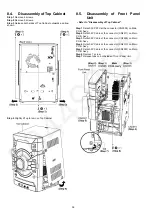
• Disassembly of Top Cabinet
• Disassembly of Front Panel Unit
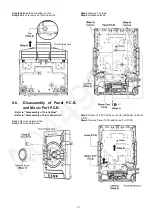
• Disassembly of Panel P.C.B. and Music Port P.C.B.
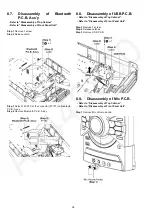
• Disassembly of Bluetooth P.C.B. Ass’y
• Disassembly of USB P.C.B.
• Disassembly of Mic P.C.B.
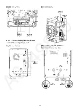
• Disassembly of Rear Panel
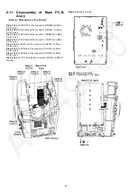
• Disassembly of Main P.C.B. Ass'y
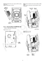
• Disassembly of SMPS Module
• Disassembly of DVD Mechanism Unit
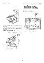
• Disassembly of Backend P.C.B. Ass'y
8.1.
Type of Screws
8.2.
Disassembly Flow Chart
Top Cabinet
Main P.C.B. Ass'y
Rear Panel
Front Panel Unit
DVD Mechanism Unit
Backend P.C.B. Ass'y
SMPS Module
Panel P.C.B. and
Music Port P.C.B.
Bluetooth P.C.B. Ass'y
USB P.C.B.
Mic P.C.B.
Summary of Contents for SA-VKX95EE
Page 5: ...5 1 4 Caution For AC Cord For GS only Figure 1 3 ...
Page 12: ...12 5 Location of Controls and Components 5 1 Remote Control Key Button Operation ...
Page 13: ...13 5 2 Main Unit Key Button Operation ...
Page 14: ...14 6 Service Mode 6 1 Service Mode Table ...
Page 15: ...15 6 2 Sales Demonstration Lock Function ...
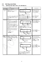
Page 20: ...20 6 5 Self Diagnostic Mode 6 5 1 Self Diagnostic Mode Table 1 For DVD Module ...
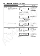
Page 21: ...21 6 5 2 Self Diagnostic Mode Table 2 For DVD Module ...
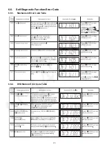
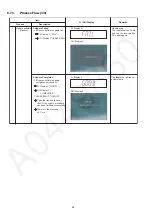
Page 22: ...22 6 5 3 Self Diagnostic Mode Table 3 For DVD Module ...
Page 35: ...35 8 3 Main Components and P C B Locations ...
Page 46: ...46 ...
Page 58: ...58 ...
Page 60: ...60 ...
Page 86: ...86 ...
Page 96: ...96 ...
Page 100: ...100 ...