background image

14

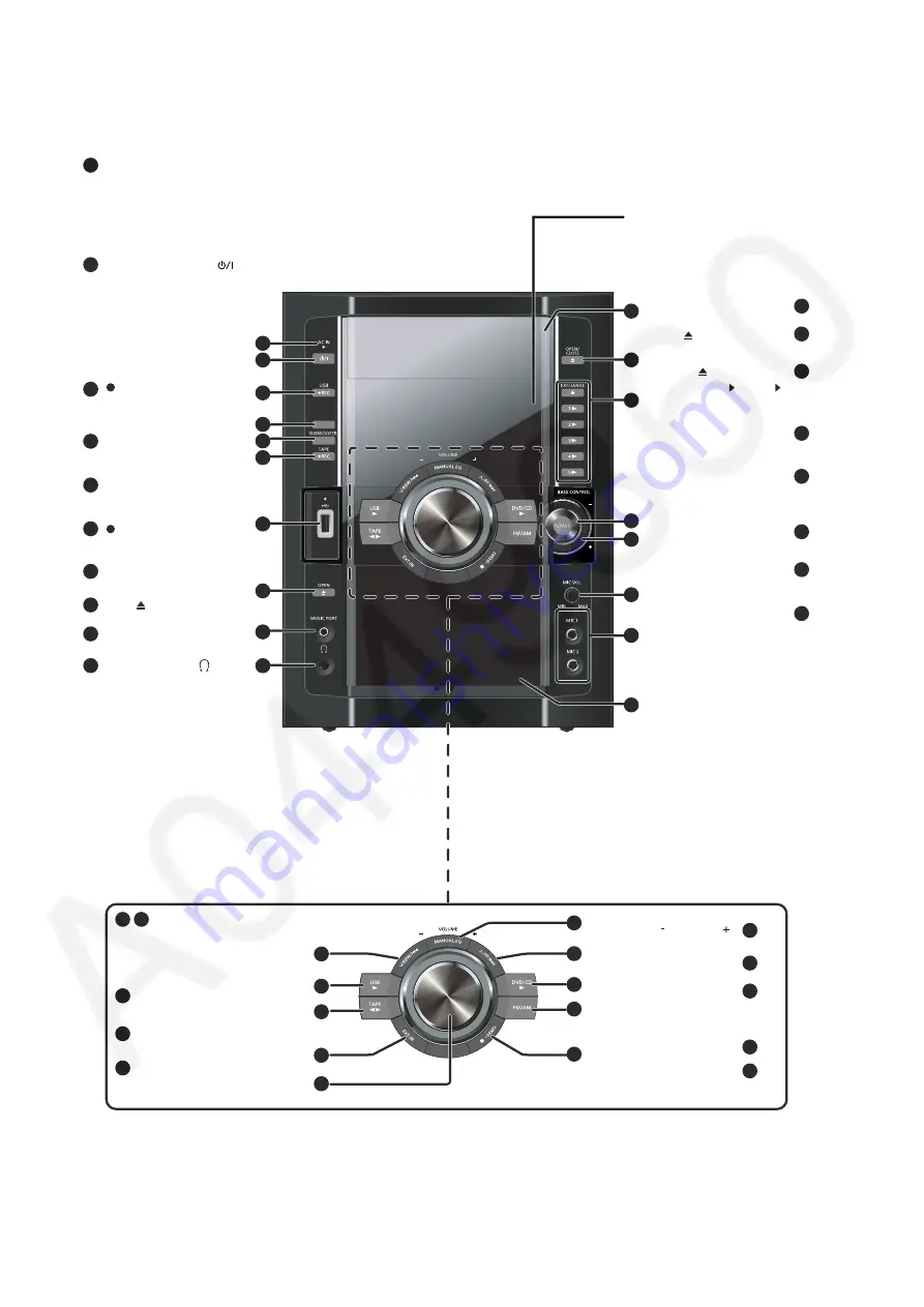
5 Location of Controls and Components

5.1.

Main Unit Key Button Operation

SURR

OUND

1

2

3

5

6

7

8

9

10

4

16

17

13

14

15

11

12

AC supply indicator 
(AC IN) 

This indicator lights when 
the unit is connected to 
the AC mains supply.

Standby/on switch (

)

Press to switch the unit 
from on to standby mode 
or vice versa.
In standby mode, the unit 
is still consuming a small 
amount of power.

[  REC, USB]

Using surround effect

3

5

6

1

2

4

7

8

Adjusting subwoofer level 

[  REC, TAPE]

USB port

Deck [ , OPEN]

9

MUSIC PORT jack

Headphone jack

Reduce the volume 
level and connect the 
headphones. Headphones 
plug type:  3.5 mm 
stereo (not included).

Avoid listening for 
prolonged periods of 
time to prevent hearing 
damage.
Excessive sound 
pressure from 
earphones and 
headphones can cause 
hearing loss.

10

11

12

16

13

14

15

17

Disc trays

[ , OPEN/CLOSE]

[ , EXCHANGE]

[1  ] to [5  ]

(disc direct play)

Enhancing bass sound 

[MIN, MIC VOL, MAX] 

Microphone

(MIC 1, MIC 2) jacks

Cassette holder

24

25

21

22

23

19

20

26

27

28

Skip, rewind, fast forward, 
Tape Program Sensor, 
sound quality adjustment, 
time adjustment

Tape playback and direction 

FM/AM selection

MUSIC PORT/AUX selection 

21

22

[   VOLUME   ]

23

19

20

24

26

27

[MANUAL EQ]

DVD/CD selector and 

playback

USB selector and playback 

Stop, DEMO function 

Remote control signal sensor

25

28

Selecting Manual EQ, 

adjusting its BASS level 

18

18

Summary of Contents for SA-VK680EE

Page 1: ...ntion of Electrostatic Discharge ESD to Electrostatic Sensitive ES Devices 6 2 2 Precaution of Laser Diode 7 2 3 Service caution based on Legal restrictions 8 2 4 Handling Precautions for Traverse Unit 9 3 Service Navigation 11 3 1 Service Information 11 4 Specifications 12 5 Location of Controls and Components 14 5 1 Main Unit Key Button Operation 14 5 2 Remote Control Key Button Operation 15 5 3...

Page 2: ... Inlet P C B 82 10 Disassembling and Assembling of Traverse Unit 84 10 1 Disassembly Procedures 84 10 2 Assembly Procedures 85 11 Service Positions 86 11 1 Checking and Repairing of Main P C B 86 11 2 Checking and Repairing Panel P C B Deck P C B Volume P C B Music Port P C B and Mic P C B 86 11 3 Checking and Repairing of D Amp P C B 89 11 4 Checking and Repairing of AC Inlet P C B SMPS P C B 90 ...

Page 3: ...3 21 1 Exploded View and Mechanical Replacement Part List 147 21 2 Electrical Replacement Part List 153 ...

Page 4: ...er with 1000 ohms volt or more sensitivity to measure the potential across the resistor 4 Check each exposed metallic part and measure the voltage at each point 5 Reverse the AC plug in the AC outlet and repeat each of the above measurements 6 The potential at any point should not exceed 0 75 volts RMS A leakage current tester Simpson Model 229 or equivalent may be used to make the hot checks leak...

Page 5: ...anufacturer Safety Ref No Part No Part Name Description Remarks 15 RGRX0070N D1 REAR PANEL 62 REXX0684 1 BLACK WIRE AC INLET SMPS 63 REXX0685 1 RED WIRE AC INLET SMPS 69 RKMX0144A K TOP CABINET 340 RD DDTX004 V TRAVERSE ASS Y RTL A2 K2CQ2CA00007 AC CORD A3 RQTX0284 R O I BOOK Ru Ur PCB13 REPX0751C SMPS P C B RTL PCB14 REPX0751C AC INLET P C B RTL DZ5701 ERZV10V511CS ZNR L5701 ELF15N035AN LINE FILT...

Page 6: ...f the assembly 3 Use only a grounded tip soldering iron to solder or unsolder ES devices 4 Use only an anti static solder removal device Some solder removal devices not classified as anti static ESD protected can generate electrical charge sufficient to damage ES devices 5 Do not use freon propelled chemicals These can generate electrical charges sufficient to damage ES devices 6 Do not remove a r...

Page 7: ... radiation power from pickup 100 µW VDE Laser radiation from the pickup unit is safety level but be sure the followings 1 Do not disassemble the pickup unit since radiation from exposed laser diode is dangerous 2 Do not adjust the variable resistor on the pickup unit It was already adjusted 3 Do not look at the focus lens using optical instruments 4 Recommend not to look at pickup lens for a long ...

Page 8: ...is used Definition The letter of PbF is printed on the PCB using the lead free solder To put lead free solder it should be well molten and mixed with the original lead free solder Remove the remaining lead free solder on the PCB cleanly for soldering of the new IC Since the melting point of the lead free solder is higher than that of the normal lead solder it takes the longer time to melt the lead...

Page 9: ...the laser diode from the electrostatic discharge damage the flexible cable of the optical pickup unit removed should be short circuited with a short pin or a clip 3 The flexible cable may be cut off if an excessive force is applied to it Use caution when handling the flexible cable 4 The antistatic FPC is connected to the new optical pickup unit After replacing the optical pickup unit and connecti...

Page 10: ...10 2 4 2 2 Human body grounding 1 Use the anti static wrist strap to discharge the static electricity form your body Figure 2 ...

Page 11: ... by supplement service manual to be filed with original service manual DVD Mechanism unit CR14D 1 This model uses DVD Mechanism Unit CR14D Micro processor EEPROM IC 1 The following components are supplied as an assembled part Micro processor IC IC2801 RFKWMVK480GC EEPROM IC IC2802 RFKWEVK480GC EEPROM IC IC8611 RFKBX0681D C Speaker system 1 For information please refer to original service manual SB...

Page 12: ...USB Port power Max 500 mA Bit rate up to 4 Mbps DivX USB Recording Bit Rate 128 kbps USB recording speed 1x Recording file format MP3 mp3 Q DISC SECTION Disc played 8 cm or 12 cm 1 DVD DVD Video DivX 6 7 2 DVD RAM DVD VR JPEG 4 7 MP3 2 7 MPEG4 5 7 DivX 6 7 3 DVD R DVD Video DVD VR JPEG 4 7 MP3 2 7 MPEG4 5 7 DivX 6 7 4 DVD R DL DVD Video DVD VR 5 DVD RW DVD Video DVD VR JPEG 4 7 MP3 2 7 MPEG4 5 7 D...

Page 13: ...13 ...

Page 14: ...dphones Headphones plug type 3 5 mm stereo not included Avoid listening for prolonged periods of time to prevent hearing damage Excessive sound pressure from earphones and headphones can cause hearing loss 10 11 12 16 13 14 15 17 Disc trays OPEN CLOSE EXCHANGE 1 to 5 disc direct play Enhancing bass sound MIN MIC VOL MAX Microphone MIC 1 MIC 2 jacks Cassette holder 24 25 21 22 23 19 20 26 27 28 Ski...

Page 15: ...imer Auto off operation setting 18 19 13 14 15 17 16 3 6 5 4 2 Turn the unit on off Clock and timer setting PLAY REC timer on off 1 Select channels and title numbers etc Enter numbers Show disc information Select a disc Play loaded discs in order 9 8 7 12 10 Cancel an item Deleting an item 13 11 Source select USB selector and playback TAPE Tape playback and direction EXT IN FM AM FM AM selection M...

Page 16: ...orders or DVD video cameras using DVD Video Format 5 Recorded using a format different from DVD Video Format therefore some functions cannot be used 6 MPEG4 data recorded with the Panasonic SD multi cameras or DVD video recorders conforming to SD VIDEO specifications ASF standard MPEG4 Simple Profile video system G 726 audio system 7 Functions added with DivX Ultra are not supported 8 A process th...

Page 17: ...aximum of 720 x 480 NTSC 720 x 576 PAL You can select up to eight types of audio and subtitles on this unit When there are more than eight groups the eighth group onwards will be displayed on one vertical line in the menu screen There may be differences in the display order on the menu screen and computer screen This unit cannot play files recorded using packet write DVD RAM Discs must conform to ...

Page 18: ... TAPE on the main unit to start recording Press REC USB on the main unit to start recording 4 Playback the portable audio equipment You can playback sound from portable audio equipment Sound from the speaker may be distorted if the portable audio equipment s equalizer if any is turned on Turn it off before you plug into the MUSIC PORT jack Preparation Reduce the volume of the unit and portable aud...

Page 19: ...ntent If you use this code to purchase DivX VOD content and then play the content on this unit you will no longer be able to play any content that you purchased using the previous code If you purchase DivX VOD content using a registration code different from this unit s code you will not be able to play this content Regarding DivX content that can only be played a set number of times Some DivX VOD...

Page 20: ...ile name File extension Still pictures JPG 1 jpg jpeg Music MP3 WMA mp3 wma Video MPEG4 2 asf 1 It may not be possible to play all the files due to the condition on how they were created 2 For Panasonic D Snap DIGA Maximum number of folders 255 Maximum number of files 4000 Maximum length of folder name 28 Maximum length of file name 28 CBI Control Bulk Interrupt is not supported Digital Cameras th...

Page 21: ...s you to erase unwanted tracks quickly and easily Erasing the recorded items No Yes mp3 002 Is it OK to delete locked Folders containing subfolders or unsupported files cannot be deleted Note Erasing items in order Playback Menu 1 Press and press OK When either one is selected other file will become invisible and cannot be deleted 2 Press DEL to delete 3 Repeat step 2 until all files are deleted 4...

Page 22: ... In self diagnostic mode Servicing the mechanism unit In self diagnostic mode Servicing the traverse unit In Self diagnosis mode 2 Reliability 2 Cycle Refer to the section 6 3 2 Self Diagnosis Mode Table 2 for more information 3 Reliability 3 Combi Main buttons Remote control unit buttons Application Note STOP 0 Error code display Refer to the section 6 4 1 Service Mode Table 1 for more informa ti...

Page 23: ...uard function beforehand written in the disk for protection of copyrights 2 CEC is the consumer electronic control used for high level user control of HDMI connected devices 3 HDCP is the specification developed to control digital audio video contents transmission for DVI or HDMI connections ...

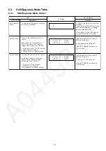
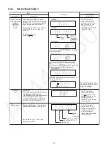
Page 24: ...ay 1 If the EEPROM version matches checksum YYYY is displayed If the version of the EEPROM does not match or not working properly NG is displayed checksum Condition 2 checksum Condition 3 Checksum value HEX applicable when the EEPROM IC is installed Firmware Version DEC Firmware different from set Firmware Version DEC To enter into Doctor Mode for checking of variuos items and displaying EEPROM an...

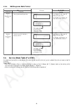
Page 25: ...nostic checking for CR14D mechanism Self Diagnostic Mode To unlock the mechanism unit for service In this mode the disassembly of CR14D can be carry out Refer to original service manual for CR14D 1 All trays are set to STOCK position 2 Mechanism set to tray 1 3 Cam gear set to HOME position Service Mode 1 In self diagnostic mode press 2 button on main unit To exit power off the main unit Press EXC...

Page 26: ...ol Key Buttons Operations FL Display Key Operation Front Key Item Description Mode Name In self diagnostic mode press 2 button on remote control To exit press button on the main unit or remote control unit Reliability 2 Traverse Cycle Test To determine playability operation In self diagnostic mode press 3 button on remote control To exit press button on the main unit or remote control unit Reliabi...

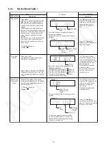
Page 27: ...wn in hexadecimal notation Display 1 Display 1 Display 2 Display 2 In STOP no disc mode press STOP button on the main unit and 0 button on the remote control unit With pointing of cursor up and down on display Error code check The latest error code stored in the EEPROM IC is displayed Note Refer to Section 8 4 DVD Self Diagnostic Function Error Code for more detailed information on the error codes...

Page 28: ...notation The above example shows the initial current is XXXmA and the measured value is YYYmA DVD laser drive current measurement Press FL Display on remote control unit for next page FL Display on values of dvd drive current Cancelled automatically 5 seconds later Display 1 Display 2 Display 1 Display 2 In STOP no disc mode press STOP button on the main unit and FUNCTIONS button on the remote con...

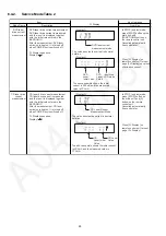
Page 29: ...ton on the main unit and 10 button on the remote control unit If the EEPROM version matches checksum YYYY is displayed If the version of the EEPROM does not match NG is displayed a If there is NO EEPROM header string OR b If there is no EEPROM no data is received by Micro processor NO is displayed EEPROM Checksum If applicable refer below Condition1 Opecon Version Display 1 Display 2 Display 3 Con...

Page 30: ... disc PAL DVD V NTSC DVD A VCD NTSC D Source Output Screen Saver NTSC NTSC disc NTSC PAL disc NTSC PAL C Source Output Screen Saver PAL NTSC disc PAL60 default NTSC PAL disc PAL Explanation of Display Individual Model Code Can play PAL disc Region code N If NTSC disc is played NTSC output 6 If NTSC disc is played PAL60 output 2 6 5 4 4 2 2 1 2 3 Region Code NTSC PAL NTSC PAL SECAM NTSC PAL PAL PAL...

Page 31: ...sion Region No 0 8 DVD Module P C B firmware version is displayed on the FL Display The firmware version can be updated using recovery disc Note It is necessary to check for firmware version before carrying out the version up using the disc CPPM CRM refers to the Content Protection for Recordable Media and Pre Recorded Media It displays the existence of the keys as 1 or 0 OK Existing of keys NG No...

Page 32: ...d separately for DVD laser and CD laser FL Display sequence Display 1 2 Press FL Display button for next page of FL Display Timer 1 reset Laser operation timer of both DVD laser and CD laser is reset all at once Timer 2 check Spindle motor operation timer Timer 2 reset Spindle motor operation timer Time is shown in 5 digits of decimal notation in a unit of 1 hour 00000 will follow 99999 Shown to t...

Page 33: ...result will be incorrect Figure 2 NO DISC is displayed unit does not play smoothly etc Check the laser drive current Replace the traverse unit Refer to the section OPTICAL PICKUP REPLACEMENT PROCEDURE in this Guide Initialize the main unit Value is more than 37 DVD 41 CD Replace with a new optical pickup if the present value is more than 37 DVD 41 CD Cause Damage due to static electricity during r...

Page 34: ... next error error reproducing disk verify error when connecting it with HDMI DVI F740 HDMI device key I2C error when writing HDMI Key device Press STOP on main into transmitter unit for next error F893 FLASH ROM IC data Firmware error DV5 0 LSI IC IC8651 Press STOP on main falsification error error unit for next error F894 EEPROM IC When failing in the access to EEPROM Press STOP on main abnormali...

Page 35: ...DV5 LSI IC IC8001 error H07 Driver IC thermal The spindle motor is abnormal short Press STOP on shut down between brushes main unit for next error H15 Disc tray open The disc tray cannot be opened it Press STOP on detection switch closes spontaneously main unit for next error failure H16 Disc tray close The disc tray cannot be closed it Press STOP on detection switch opens spontaneously main unit ...

Page 36: ...2 not available Diagnosis Contents Description of error Automatic FL Display Remarks Error Code F650 USB device Devices Devices other than the mass storage Press STOP on main other than mass class are connected unit for next error storage F651 USB device Non Full The device that the transfer rate did not Press STOP on main Speed Device correspond to Full Speed was unit for next error connected F65...

Page 37: ...n time out occurs Press EXCHANGE on main unit for next error DOWN Down operation faulty The down operation cannot complete when time out Press EXCHANGE on main unit for next error OPEN Open operation faulty The open operation cannot complete when time out Press EXCHANGE on main unit for next error CLOSE Closeoperation faulty The open operation cannot complete when time out Press EXCHANGE on main u...

Page 38: ... unit displays LOCKED while the lock function mode is entered Prohibiting operation of selector and disc 1 Select the DVD CD function 2 At POWER ON condition press and hold down the button and the power button on the main unit for at least three sec onds The message LOCKED appears when the function is activated Note The following buttons are invalid and the main unit displays LOCKED while the lock...

Page 39: ...or of F61 and or F76 after power up of the unit It is for purpose of troubleshooting and checking in SMPS D Amp Main P C B 7 1 1 Block Diagram Figure 1 Speaker Out DC Detect SUBWOOFER FRONT R FRONT L 30V Detect 30V_SENSE SYS6V FAN Detect D AMP P C B SMPS P C B MAIN P C B MICRO P DCDET 2 DCDET1 2 F61 SYS6V T 18V Fan Detect emperature Detect DCDET 1 ...

Page 40: ...on feedback loop x If the fan not proper connected F61 will trigger when the volume increase x If the fan is not working check for fan circuit Check the soldering of the SMPS P C B x Is there any solder crack at area Q5860 Q5861 Q5862 TH5860 x C x 18V at ZJ2701 Pin 8 9 heck all the supply line 30V Re connect the Fan to CN2810 Fan Q2948 Q2949 circuit Q2942 Q2943 Touch up the solder crack area Chang...

Page 41: ...t Location 7 1 3 1 SMPS P C B Figure 2 SMPS P C B Feedback circuit PC5720 D5725 SMPS P C B 30V Detect QR5801 QR5802 Feedback Circuit IC5801 Q5802 D5806 Temperature Detect Q5860 Q5681 Q5862 Temperature Detect TH5860 ...

Page 42: ...42 7 1 3 2 D Amp P C B Figure 3 D Amp P C B Audio Digital Power Amp IC IC5000 Audio Digital Power Amp IC IC5200 D Amp P C B SPEAKER OUTPUT ...

Page 43: ...43 7 1 3 3 Main P C B Figure 4 Main P C B Transistor Q2942 Q2943 Q2948 Q2949 Fan Circuit Switching Regulator IC IC4000 Fuse Protector FP2091 T2900 D2901 Connector CN2807 ...

Page 44: ...44 7 1 3 4 D Amp IC Configuration Figure 5 D Amp IC Configuration VK680EE Pin 10 Subwoofer Subwoofer IC5200 Pin 14 Pin 10 Front Right IC5000 Pin 14 Front Left ...

Page 45: ...C8251 Pin 15 to 16 17 18 Check for solder short and or component missing damaged a Check connection from DVD Module to Traverse unit FP8251 3 Disc not spinning 4 Traverse not moving 5 Traverse and spindle abnormal movement b Check motor driver circuitry on the voltages and control signals Compare the above with OK condition DVD Module P C B IC8251 Check for solder short and or component damaged 6 ...

Page 46: ...t Prepare service tools before process service position Service Tools Remarks Main P C B CN2808 D Amp P C B CN5050 REEX0930 17P FFC M RTL Main P C B ZJ2701 SMPS P C B CN5802 REXX0680 11P Cable M RTL SMPS P C B H5801 D Amp P C B CN5500 REXX0683 8P Cable M RTL ...

Page 47: ...lowing index when checks or replacement are required Disassembly of Top Cabinet Disassembly of DVD Mechanism Unit CR14D Disassembly of DVD Module P C B Disassembly of Rear Panel Disassembly of Front Panel Assembly Disassembly of USB P C B Disassembly of Mic P C B Disassembly of Panel P C B Volume P C B Remote Sensor P C B Side Bar L R LED P C B Disassembly of Music Port P C B Disassembly of CD Lid...

Page 48: ...48 ...

Page 49: ...p IC IC5200 9 24 Switching Regulator IC IC5701 9 25 Switching Regulator Diode D5702 9 26 Regulator Diode D5801 9 27 Regulator Diode D5802 9 28 Regulator Diode D5803 9 22 Main P C B 9 23 SMPS P C B 9 8 Mic P C B 9 10 USB P C B 9 11 Music Port P C B 9 12 CD Lid 9 13 Deck Mechanism Unit 9 14 Deck P C B 9 17 Cassette Lid 9 15 Deck Mechanism P C B 9 16 Deck Mechanism 9 18 Rectification for Tape Jam Pro...

Page 50: ...50 9 2 Main Components and P C B Location ...

Page 51: ...Top Cabinet Step 1 Remove 3 screws on each side of the main unit Step 2 Remove 5 screws Step 3 Lift the sides of top cabinet outwards as arrow shown Step 4 Push the top cabinet backwards as arrow shown to release the catches ...

Page 52: ...to Step 5 of Item 9 3 Step 1 Remove 1 screw at rear panel Step 2 Detach 50P FFC cable at the connector CN2801 on Main P C B Step 3 Detach 11P FFC cable at the connector CN2805 on Main P C B Step 4 Detach 5P cable at the connector CN1113 on USB P C B Step 5 Release the claws outwards on both sides ...

Page 53: ...Unit CR14D from the catches and locators Step 7 Lift up DVD Mechanism Unit CR14D in the direction of arrow Caution During assembling ensure that the DVD Mecha nism Unit CR14D is seated properly at the locator Step 8 Detach 7P FFC at the connector FP8251 Step 9 Detach 26P FFC at the connector FP8531 ...

Page 54: ...ssis as arrow shown 9 5 Disassembly of DVD Module P C B Follow the Step 1 to Step 5 of Item 9 3 Follow the Step 1 to Step 9 of Item 9 4 Step 1 Remove 3 screws Step 2 Remove the shield plate unit Step 3 Remove DVD Module P C B 9 6 Disassembly of Rear Panel Follow the Step 1 to Step 5 of Item 9 3 Step 1 Remove 11 screws at rear panel Step 2 Release 2 catches from the each side of the rear panel ...

Page 55: ...Step 1 Detach 27P FFC at the connector CN2807 on Main P C B Step 2 Detach 2P cable at the connector CN2813 on Main P C B Step 3 Detach 5P cable at the connector CN1113 on USB P C B Step 4 Detach 10P FFC at the connector CN2752 on Main P C B Step 5 Detach 12P FFC at the connector CN2751 on Main P C B Step 6 Detach 10P FFC at the connector CN2806 on Main P C B Step 7 Detach 2P cable at the connector...

Page 56: ...ly catched Step 10 Release the tabs at the bottom Caution Do not exert strong force when releasing the tabs Step 11 Remove 1 screw to remove ground wire Step 12 Remove front panel assembly in the direction of arrow 9 8 Disassembly of Mic P C B Follow the Step 1 to Step 5 of Item 9 3 Follow the Step 1 to Step 12 of Item 9 7 Step 1 Remove Mic knob ...

Page 57: ...sembly of Panel P C B Volume P C B Remote Sen sor P C B Side Bar L LED P C B and Side Bar R LED P C B Follow the Step 1 to Step 5 of Item 9 3 Follow the Step 1 to Step 12 of Item 9 7 Follow the Step 2 of Item 9 8 Step 1 Remove volume knob Step 2 Detach 7P cable at the connector CN6702 on Mic P C B Step 3 Remove 9 screws at Panel P C B ...

Page 58: ...58 Step 4 Remove 2 screws on Volume P C B Step 5 Release 2 catches at Panel P C B Step 6 Release 6 catches at Volume P C B Step 7 Release 2 catches at Remote Sensor P C B ...

Page 59: ...P C B Step 10 Detach Side Bar R P C B at the connector CN6012 on Panel P C B Step 11 Remove the Side Bar L P C B and Side Bar R P C B Caution During assembling ensure that the diodes shown on Volume P C B are in upright position Caution During assembling ensure that Dynamic Bass Button is seated properly 9 10 Disassembly of USB P C B Follow the Step 1 to Step 5 of Item 9 3 Follow the Step 1 to Ste...

Page 60: ...e USB P C B 9 11 Disassembly of Music Port P C B Follow the Step 1 to Step 5 of Item 9 3 Follow the Step 1 to Step 12 of Item 9 7 Step 1 Remove 2 screws at Music Port P C B Step 2 Release 2 catches Step 3 Lift up to remove Music Port P C B 9 12 Disassembly of CD Lid Follow the Step 1 to Step 5 of Item 9 3 Follow the Step 1 to Step 12 of Item 9 7 Step 1 Remove the spring as arrow shown in order of ...

Page 61: ...as arrow shown 9 13 Disassembly of Deck Mecha nism Unit Follow the Step 1 to Step 5 of Item 9 3 Follow the Step 1 to Step 12 of Item 9 7 Step 1 Remove 4 screws at Deck Mechanism Unit Step 2 Push the lever upward as arrow shown to open the cas sette lid Step 3 Remove Deck Mechanism Unit in the direction of arrow ...

Page 62: ...Remove shield plate Step 3 Desolder 2P wire at the Capstan Motor Ass y Step 4 Lift up remove Deck P C B Caution During assembling ensure connector CP1301 at Deck P C B is seated properly connected to the head connector cable 9 15 Disassembly of Deck Mecha nism P C B Follow the Step 1 to Step 5 of Item 9 3 Follow the Step 1 to Step 12 of Item 9 7 Follow the Step 1 to Step 3 of Item 9 13 ...

Page 63: ... screw Step 3 Release 4 catches Step 4 Remove Deck Mechanism P C B Caution During assembling ensure that the Deck Mecha nism P C B is seated properly with the guide of the loca tors 9 16 Disassembly of Deck Mecha nism Follow the Step 1 to Step 5 of Item 9 3 ...

Page 64: ...d Head Block Sub Ass y Step 1 Release catch to remove the Pinch Roller F Assy Step 2 Release catch to remove the Pinch Roller R Assy Step 3 Release the catches at the side of head connector Step 4 Detach the head connector as arrow shown Caution Avoid exerting strong force as it may damage the FFC Step 5 Remove 2 screws Step 6 Remove Head Block Sub Ass y as arrow shown ...

Page 65: ...16 1 Disassembly of Capstan Motor Ass y and Capstan Belt A Step 1 Remove 3 screws Step 2 Lift up to remove the Sub Chassis Ass y Step 3 Remove 2 screws to remove Capstan Motor Ass y Caution Support Capstan Motor Ass y by hand to prevent it from falling during removal and assembly of Capstan Motor Ass y ...

Page 66: ...Assembly of Capstan Motor Ass y and Capstan Belt A Step 1 Coil Capstan Belt A to Flywheel F Ass y Flywheel L and the 2 bosses temporarily as diagram shown Caution Keep Capstan Belt A away from grease during assembly of Capstan Belt A ...

Page 67: ... Install the Sub Chassis Ass y to the Deck Mechanism Unit Caution Ensure the Sub Chassis Ass y seats properly on the bosses Step 5 Fix 3 screws Step 6 Release Capstan Belt A to the pulley of Capstan Motor Ass y as diagram shown 9 16 3 Replacement of Winding Belt Follow the Step 3 to Step 4 of item 9 16 1 Follow the Step 1 to Step 4 of item 9 16 2 Disassembly of Winding Belt ...

Page 68: ... 2 Remove Flywheel L Ass y Step 3 Remove the Winding Lever Step 4 Remove the Thrust Spring Step 5 Remove the Winding Arm Ass y Step 6 Remove the Flywheel F Ass y Step 7 Remove the Winding Belt Caution Keep Thrust Spring in a safe place for assembling purpose Assembly of Winding Belt ...

Page 69: ... Belt to the Winding Arm Ass y and the 2 bosses temporarily as diagram shown Step 3 Install Flywheel F Ass y Caution Ensure that the boss and the marking hole of the Main Gear are positioned such that they form a horizontal line parallel to the Deck Mechanism Unit ...

Page 70: ...he Winding Arm Ass y is pulled towards to the right as arrow shown to enable full insertion of the Winding Lever The Winding Lever must be seated on the Main Gear as diagram shown Caution 2 Ensure that the Winding Lever is firmly inserted and properly catched on the tape side as diagram shown ...

Page 71: ... Release the Winding Belt on Flywheel F Ass y as dia gram shown Step 7 Install Flywheel L Ass y 9 16 4 Disassembly of Main Gear Follow the Step 3 to Step 4 of item 9 16 1 Follow the Step 1 to Step 4 of item 9 16 2 Follow the Step 1 to Step 6 of item 9 16 3 Step 1 Remove Main Gear using tweezers ...

Page 72: ...of Item 9 3 Follow the Step 1 to Step 12 of Item 9 7 Follow the Step 1 to Step 3 of Item 9 13 Step 1 Remove the spring Step 2 Push the cassette lid in the direction of arrows 9 18 Rectification for Tape Jam Problem Follow the Step 1 to Step 5 of Item 9 3 Step 1 Rotate the flywheel F in the direction of the arrow to remove it Step 2 Push the lever upward and open the cassette lid Note Follow Disass...

Page 73: ...nel Step 2 Detach 17P FFC at the connector CN5050 on D Amp P C B Step 3 Detach 8P cable at the connector CN5500 on D Amp P C B Step 4 Remove 2 screws at D Amp P C B Inner chassis assembly Step 5 Lift up the D Amp P C B together with the inner chassis assembly as arrow shown Step 6 Remove 2 screws on D Amp P C B Step 7 Lift up D Amp P C B as arrow shown ...

Page 74: ... side of D Amp P C B Step 3 Remove 1 screw Step 4 Remove TR Spring in the direction of arrow shown Step 5 Remove Audio Digital Power Amp IC IC5000 Caution During replacement of the part avoid touching the heatsink it may lead to injuries 9 20 1 Assembly of Audio Digital Power Amp IC IC5000 Step 1 Mount the Audio Digital Power Amp IC IC5000 on to D Amp P C B Step 2 Screw back TR Spring to hold the ...

Page 75: ... unit Caution During replacement of the part avoid touching the heatsink it may lead to injuries 9 21 1 Assembly of Audio Digital Power Amp IC IC5200 Step 1 Mount the Audio Digital Power Amp IC IC5200 on to D Amp P C B Step 2 Screw back TR Spring to hold the Audio Digital Power Amp IC IC5200 onto the Heatsink Power Unit Step 3 Solder the pins of Audio Digital Power Amp IC Step 4 Use a blower to re...

Page 76: ...N2810 on SMPS P C B Step 3 Remove 2 screws on Main P C B Step 4 Remove 4 screws at rear panel Step 5 Remove Main P C B according to the arrow shown 9 23 Disassembly of SMPS P C B Follow the Step 1 to Step 5 of Item 9 3 Follow the Step 1 to Step 7 of Item 9 4 Follow the Step 1 to Step 5 of Item 9 19 ...

Page 77: ...r 2 wires pins red and black Step 5 Remove SMPS P C B Caution During assembling ensure that SMPS P C B is seated properly at the locators 9 24 Replacement of Switching Reg ulator IC IC5701 Follow Step 1 to Step 5 of Item 9 3 Follow Step 1 to Step 7 of Item 9 4 Follow Step 1 to Step 5 of Item 9 19 Follow Step 1 to Step 5 of Item 9 23 9 24 1 Disassembly of Switching Regula tor IC IC5701 ...

Page 78: ...egulator IC IC5701 on to SMPS P C B Caution Ensure pins of the switching regulator IC IC5701 are properly seated on SMPS P C B Step 3 Solder pins of the Switching Regulator IC IC5701 on the solder side of SMPS P C B Step 4 Screw the Switching Regulator IC IC5701 to the Heat sink Unit B Caution Ensure the switching regulator IC IC5701 is tightly screwed to the Heatsink Unit B 9 25 Replacement of Re...

Page 79: ...ay lead to injuries 9 25 2 Assembly of Rectifier Diode D5702 Step 1 Apply grease to the Heatsink Unit B Step 2 Screw the Rectifier Diode D5702 to the Heatsink Unit B Caution Ensure the Rectifier Diode D5702 is well tight ened to the Heatsink Unit B Step 3 Mount the Heatsink Unit B Rectifier Diode D5702 on to SMPS P C B Caution Ensure pins of the Rectifier Diode D5702 is properly seated on SMPS P C...

Page 80: ...ching the heatsink it may lead to injuries 9 26 2 Assembly of Regulator Diode D5801 Step 1 Apply grease to the Heatsink Unit C Step 2 Mount screw the Regulator Diode D5801 to the Heatsink Unit C on the SMPS P C B Caution Ensure the Regulator Diode D5801 is well tight ened to the Heatsink Unit C Step 3 Solder pins of the Regulator Diode D5801 on the sol der side of SMPS P C B Caution Ensure pins of...

Page 81: ...eatsink Unit C on SMPS P C B Caution Ensure the Regulator Diode D5802 is well tight ened to the heatsink unit C Step 3 Solder pins of the Regulator Diode D5802 on the sol der side of SMPS P C B Caution Ensure pins of the Regulator Diode D5802 is properly seated and soldered on SMPS P C B 9 28 Replacement of Regulator Diode D5803 Follow Step 1 to Step 5 of Item 9 3 Follow Step 1 to Step 7 of Item 9...

Page 82: ...ator diode D5803 to the Heat sink Unit C on SMPS P C B Caution Ensure the Regulator Diode D5803 is well tight ened to the Heatsink Unit C Step 3 Solder pins of the Regulator Diode D5803 on the sol der side of SMPS P C B Caution Ensure pins of the regulator diode D5803 are properly seated and soldered on SMPS P C B 9 29 Disassembly of AC Inlet P C B Follow the Step 1 to Step 5 of Item 9 3 Step 1 Re...

Page 83: ...ift up the AC Inlet P C B Step 6 Flip over the AC Inlet P C B and desolder 2 wires pins red and black Caution During assembling ensure the P C B is seated properly at the locators Caution Remember to use tie wraps to tie red black wires between AC Inlet P C B to the chassis ...

Page 84: ... Table 1 to set to Service Mode 2 10 1 Disassembly Procedures Step 1 Release the catch and push the guide as arrows shown to open both grooves Step 2 Detach the FFC wires from the adhesive areas Caution Do not pull the FFC wire to remove the traverse unit assem bly as it may cause damage to the slot ...

Page 85: ...embly Procedures Step 1 Slot the traverse unit assembly into the guides as arrow shown Note Ensure the bosses fix exactly onto the guides Step 2 Place down the traverse unit assy Step 3 Fix the FFC wires by using the adhesive tapes Step 4 Release the catch and push the guide as arrows shown to close both grooves ...

Page 86: ...tep 2 Detach 27P FFC at the connector CN2807 on Main P C B Step 3 Detach 2P cable at the connector CN2813 on Main P C B Step 4 Detach 5P cable at the connector CN1113 on USB P C B Step 5 Detach 10P FFC at the connector CN2752 on Main P C B Step 6 Detach 12P FFC at the connector CN2751 on Main P C B Step 7 Detach 10P FFC at the connector CN2806 on Main P C B Step 8 Detach 2P cable at connector CN28...

Page 87: ... C B Step 15 Remove 2 screws on USB bracket Step 16 Remove 2 screws on Music Port P C B Step 17 Remove 4 screws at Deck Mechanism unit Step 18 Remove Mic P C B Step 19 Remove USB P C B with USB bracket Step 20 Remove Music Port P C B Step 21 Push the lever upward as arrow shown to open the cassette lid assembly Step 22 Remove Deck Mechanism unit ...

Page 88: ...ctor CN2813 on Main P C B Step 28 Connect 5P cable at connector CN1113 on USB P C B Step 29 Connect 10P FFC at connector CN2806 on Main P C B Step 30 Connect 2P cable at connector CN2812 on Main P C B Step 31 Connect 10P FFC at the connector CN2752 on Main P C B Step 32 Connect 12P FFC at the connector CN2753 on Main P C B Step 33 Check and repair panel P C B Deck P C B Volume P C B Music Port P C...

Page 89: ...onnector CN5050 on D Amp P C B Step 4 Detach 8P cable at connector CN5500 on D Amp P C B Step 5 Remove 2 screws at Inner chassis assembly Step 6 Remove 4 screws at the rear panel Step 7 Lift up the D Amp P C B together with the Inner chassis assembly as arrow shown Step 8 Remove 2 screws from D Amp P C B Step 9 Lift up D Amp P C B as arrow shown ...

Page 90: ...iginal cable with extension cable REXX0683 8P cable from H5801 to CN5500 Step 16 Connect extension cable REEX0930 17P cable from CN2808 to CN5050 Step 17 Check and repair D Amp P C B according to the dia gram shown 11 4 Checking and Repairing of AC Inlet P C B SMPS P C B Follow Step 1 to Step 9 of item 11 3 Step 1 Detach wire connector at connector CN5802 on SMPS P C B Step 2 Remove 4 screws on SM...

Page 91: ...at the connector CN2805 on Main P C B Step 12 Connect 5P cable at the connector CN1113 on USB P C B Step 13 Position SMPS and AC Inlet P C B acccording to the diagram shown Step 14 Attach original cable with extension cable REXX0680 11P cable from ZJ2701 to CN5050 Step 15 Connect extension cable REEX0930 17P cable from CN2802 to CN5050 Step 16 Attach original cable with extension cable REEX0683 8P...

Page 92: ... Jack output jig Figure 2 c Frequency indicator d Electrical voltmeter e Digital frequency counter f Oscilloscope Figure 1 Figure 2 12 2 Tape Speed Adjustment 1 Connect the frequency indicator to the R ch of the headphone output jig Figure 3 2 Insert the test tape QZZCWAT 3 Playback the middle portion of the test tape QZZCWAT 4 Adjust the motor screw so that the following output level is produced ...

Page 93: ...de Repeat pressing the buttons till the recording pause mode is activated 5 Check that the output level is within the standard range Standard Range 14 4mV Figure 5 12 4 Bias Frequency Check 1 Connect the digital frequency counter to Pin 3 signal Pin 1 ground Figure 6 2 Set to TAPE mode 3 Insert a normal blank cassette tape QZZCRA and press O REC on main unit 4 Check that the output frequency is wi...

Page 94: ...3 84 85 86 87 88 89 90 91 92 93 94 95 96 97 98 99 100 CD PLAY 0 1 0 1 1 3 3 4 0 9 2 4 0 1 1 9 0 1 0 5 1 8 3 4 1 4 1 4 1 9 1 9 1 7 1 7 1 7 1 7 REF NO MODE 101 102 103 104 105 106 107 108 109 110 111 112 113 114 115 116 117 118 119 120 CD PLAY 0 0 0 3 0 1 0 3 2 1 3 3 0 1 2 3 1 7 2 5 2 5 2 5 2 5 2 5 2 5 2 4 2 4 2 4 2 4 REF NO MODE 121 122 123 124 125 126 127 128 129 130 131 132 133 134 135 136 137 13...

Page 95: ...E 1 2 3 4 5 6 7 8 9 10 11 12 13 14 15 16 CD PLAY 1 7 1 7 0 9 1 7 3 1 3 4 3 4 3 4 0 9 0 1 0 1 5 2 5 2 5 2 0 0 REF NO MODE 1 2 3 4 5 6 7 8 9 10 11 12 13 14 15 16 CD PLAY 2 6 2 6 0 2 6 0 5 2 5 2 0 1 4 1 7 1 6 1 7 3 4 0 5 2 0 REF NO MODE 1 2 3 4 CD PLAY 3 1 1 3 0 1 0 1 REF NO MODE 1 2 3 4 5 CD PLAY 3 1 3 4 0 1 0 1 0 REF NO MODE 1 2 3 4 5 6 7 8 CD PLAY 0 1 0 1 0 1 0 1 3 3 3 3 0 1 3 4 REF NO MODE 1 2 3 ...

Page 96: ... 1 3 0 1 2 9 1 3 2 0 1 8 2 5 2 6 2 5 1 8 0 9 3 2 REF NO MODE 1 2 3 4 5 6 CD PLAY 1 6 0 1 1 7 1 7 3 4 1 7 REF NO MODE 1 2 3 4 5 6 7 8 CD PLAY 0 1 5 2 5 2 0 1 3 4 2 4 1 7 1 7 REF NO MODE E C B E C B E C B E C B E C B CD PLAY 1 0 0 0 4 1 5 0 0 9 1 1 0 0 4 1 5 0 0 9 1 5 0 0 9 REF NO MODE E C B E C B E C B E C B E C B CD PLAY 0 1 5 1 0 1 5 1 0 1 5 1 1 6 3 7 2 2 4 3 1 9 3 7 0 1 0 3 0 1 REF NO MODE E C B...

Page 97: ...CD PLAY 0 0 0 0 0 5 0 5 1 5 1 0 0 5 1 0 5 1 5 1 0 0 0 0 0 0 STANDBY 0 0 0 0 0 5 0 5 0 5 1 0 0 5 1 0 5 1 5 1 0 0 0 0 0 0 REF NO MODE 61 62 63 64 65 66 67 68 69 70 71 72 73 74 75 76 77 78 79 80 CD PLAY 0 1 5 1 5 1 0 5 1 0 5 1 0 0 0 0 3 2 0 5 4 4 0 0 0 0 2 0 0 STANDBY 0 1 5 1 5 1 0 5 1 0 5 1 0 0 0 0 3 2 0 6 4 4 0 0 0 0 2 0 0 REF NO MODE 81 82 83 84 85 86 87 88 89 90 91 92 93 94 95 96 97 98 99 100 CD ...

Page 98: ...23 24 25 26 27 28 29 30 31 32 CD PLAY 2 3 0 0 1 6 0 1 5 0 0 1 6 1 6 0 2 3 STANDBY 2 3 0 0 1 3 0 1 3 0 0 1 4 1 4 0 2 3 REF NO MODE 1 2 3 4 5 CD PLAY 11 8 5 2 0 1 0 2 5 STANDBY 12 6 5 2 0 1 0 2 5 REF NO MODE 1 2 3 4 5 6 7 8 9 10 11 12 13 14 15 16 CD PLAY 5 3 2 7 0 0 2 8 2 7 0 6 0 6 2 7 2 7 2 7 2 7 2 7 2 7 2 7 2 7 STANDBY 5 3 2 7 0 0 2 8 2 7 0 6 0 6 2 7 2 7 2 7 2 7 2 7 2 7 2 7 2 7 REF NO MODE E C B E...

Page 99: ...E C B E C B E C B E C B CD PLAY 0 0 4 4 9 1 6 7 9 1 0 9 1 0 1 0 0 1 0 3 0 5 1 0 1 STANDBY 0 5 2 0 9 2 6 7 9 2 0 9 1 0 1 0 0 1 0 3 0 5 1 0 1 REF NO MODE E C B E C B E C B E C B E C B CD PLAY 1 9 5 2 2 6 9 1 11 6 9 7 9 1 11 7 9 8 5 3 1 5 5 0 7 5 9 1 8 2 STANDBY 1 9 5 2 2 6 9 1 11 6 9 7 9 1 12 6 9 8 5 3 1 6 5 0 7 5 9 2 8 2 REF NO MODE E C B E C B E C B E C B E C B CD PLAY 9 1 11 7 9 8 0 5 1 0 0 0 0 0...

Page 100: ... PANEL P C B IC6601 IC6601 IC6601 Q6641 REF NO MODE 1 2 3 4 5 CD PLAY 6 2 0 0 0 0 STANDBY 6 2 0 0 0 0 REF NO MODE 1 2 3 4 5 6 7 8 9 10 11 12 13 14 15 16 17 18 19 20 CD PLAY 0 1 0 7 5 2 4 4 0 5 1 0 0 1 0 1 6 1 0 9 1 0 0 0 1 0 3 8 0 3 4 4 5 2 STANDBY 0 1 0 7 5 2 4 4 0 5 1 0 0 1 0 1 6 2 0 9 2 0 0 0 1 0 3 8 0 3 4 4 5 2 REF NO MODE 21 22 CD PLAY 0 7 0 1 STANDBY 0 7 0 1 REF NO MODE E C B E C B E C B E C...

Page 101: ...0 29 0 20 6 29 3 8 9 0 29 3 19 2 29 3 0 1 8 9 29 3 29 0 29 0 0 29 0 STANDBY 2 5 0 0 29 0 0 29 0 20 6 29 3 8 9 0 29 3 19 2 29 3 0 1 8 9 29 3 29 0 29 0 0 29 0 REF NO MODE 21 22 23 CD PLAY 0 0 2 6 STANDBY 0 0 2 6 REF NO MODE 1 2 3 4 5 6 7 8 9 10 11 12 13 14 CD PLAY 0 5 2 4 9 0 2 7 2 2 0 2 5 2 6 2 6 2 5 2 5 2 6 5 2 STANDBY 0 5 2 4 9 0 2 7 2 2 0 2 5 2 6 2 6 2 5 2 5 2 6 5 2 REF NO Q5601 MODE E C B E C B...

Page 102: ...19 9 19 9 19 2 0 17 0 0 1 21 9 2 2 22 0 0 5 8 0 STANDBY 5 9 6 6 5 6 19 9 19 9 19 2 0 16 8 0 1 21 8 2 2 22 0 0 5 8 0 REF NO MODE E C B E C B E C B E C B E C B CD PLAY 1 3 0 0 7 0 0 0 7 0 5 2 0 0 3 2 0 5 0 5 0 0 STANDBY 1 3 0 0 7 0 0 0 7 0 5 2 0 0 3 2 0 5 0 5 0 0 REF NO MODE E C B E C B CD PLAY 0 4 5 0 0 0 1 5 STANDBY 1 5 1 5 0 0 0 5 Q5803 Q5720 Q5721 Q5722 Q5802 SA VK680EE SMPS P C B QR5801 QR5802 ...

Page 103: ...div WF No IC2803 3 4 PLAY 0 4Vp p 100usec div WF No IC2803 6 PLAY 1 5Vp p 500usec div WF No IC2803 9 10 PLAY 2Vp p 500usec div WF No IC2103 7 PLAY 1 9Vp p 500usec div WF No IC2801 13 PLAY 5Vp p 50nsec div WF No IC2801 15 PLAY 3 2Vp p 20nsec div WF No IC2900 21 PLAY 1 5Vp p 20usec div WF No IC2900 8 11 PLAY 1 1Vp p 20usec div WF No IC2900 15 PLAY 0 76Vp p 20usec div WF No IC2900 18 PLAY 1 5Vp p 20u...

Page 104: ...ec div WF No IC5500 4 PLAY 6 8Vp p 5msec div WF No IC5500 6 PLAY 5 2Vp p 500nsec div WF No IC5500 8 PLAY 5 6Vp p 500nsec div WF No IC5799 2 PLAY WF No IC5799 3 PLAY 2Vp p 5usec div WF No IC6601 5 PLAY 1 5Vp p 1usec div 9 6Vp p 5usec div WF No IC5799 5 PLAY 240Vp p 50usec div WF No IC5899 1 2 3 PLAY 1 65Vp p 5msec div WF No IC5701 1 PLAY 400Vp p 2usec div WF No IC5701 4 6 PLAY 2Vp p 5usec div WF No...

Page 105: ...PLAY 6 4Vp p 5usec div WF No IC8001 62 63 64 PLAY 5 6Vp p 2usec div WF No IC8001 129 PLAY 0 72Vp p 20usec div WF No IC8001 130 PLAY 0 72Vp p 20usec div WF No IC8001 131 PLAY 0 42Vp p 20usec div WF No IC8001 138 PLAY 1 05Vp p 20usec div WF No IC8001 139 PLAY 0 9Vp p 20usec div WF No IC8001 151 PLAY 6Vp p 2usec div WF No IC8001 152 PLAY 6 4Vp p 500nsec div WF No IC8422 1 PLAY 1 5Vp p 500usec div WF ...

Page 106: ...01AHL 2SB1218ARL UNR521100L 2SA207700L UNR221400L B1CFHA000002 B1GBCFJJ0051 B1GDCFGA0018 B1GBCFGH0001 B1GDCFJJ0047 B1GBCFJN0033 B1GDCFJJ0002 B1GDCFGH0002 B0ACCK000005 Cathode Anode A Ca MA2J7280GL MA2J1110GL MA2C16500E Cathode Anode A Ca B0HBSM000043 B0BC5R1A0266 B0BC6R100010 Cathode Anode A Ca B0JCPD000025 B0HCSP000001 B0FBAR000041 MAZ8051GML C1AA00000612 MAZ8075GML B0BC035A0007 B0BC8R2A0266 B0BC...

Page 107: ...05 OC EN IN IN OUT OUT 6 OUT C0DBZYY00266 USB HIGH SIDE SWITCH CN1113 1 5 FP9001 CN1113 2 4 FP9001 CN1113 3 FP9001 D 2 5V IC8695 IC8691 MCK NWE NCAS NRAS NCSM 190 189 188 181 185 ADDRESS MEMORY DATA MEMORY MA11 DQM3 MA10 MA9 MA8 MA7 MA6 MA5 MA4 MA3 MA2 MA1 MA0 MDQ15 MDQ14 MDQ13 MDQ12 MDQ11 MDQ10 MDQ9 MDQ8 MDQ7 MDQ6 MDQ5 MDQ4 MDQ3 MDQ2 MDQ1 MDQ0 160 162 164 168 170 172 176 178 177 175 171 169 201 2...

Page 108: ...2 e3 f3 F2 e4 f4 F1 e1 f1 20 FP8531 VREF A a FP8531 26 D d 17 FP8531 15 FP8531 C c B b 25 FP8531 OPTICAL PICKUP UNIT LD DRIVE Q8561 Q8562 INVERTER Q8565 SWITCH Q8563 SWITCH Q8564 LD DRIVE Q8551 Q8552 VO2 VO2 VO1 11 12 13 2 VCC1 CH2 CH2 CH1 CH1 BIAS2 LDIN 24 25 1 BIAS1 SHIFT LEVEL SHIFT LEVEL VO1 OPOUT VIN3 VIN1 VIN2 TRIN 14 6 23 28 2 3 26 4CH MOTOR DRIVER 27 MUTE CH3 MUTE CH1 2 9 20 MUTE CH4 D 3 3...

Page 109: ...TTOM D6511 VOL LED TOP VR6630 BASS CONTROL JOG 19 9 CN6001 CN2807 20 8 CN6001 CN2807 VR6500 VOLUME JOG 22 6 CN6001 CN2807 14 CN6001 CN2807 8 J6501B J6501A 15 13 CN6001 CN2807 1 J6001B J6001 2 J6501B J6501A DVREF REMOTE CONTROL SENSOR Z6601 VREF POWER S6100 SUBW S6104 USB REC S6101 SURROUND S6103 TAPE REC S6106 H BASS S6108 2 CN6702 ZJ6601 63 TAPE EJECT 18 10 CN6001 CN2807 9 2 CN6807 CN2806 MIC SW ...

Page 110: ...SYSTEM CONTROL IN R1 2 C0AABB000125 IC2804 OP AMP 5 6 7 3 1 2 5 4 3 2 1 6 7 L R JK6800 HEADPHONE 3 8 CN6807 CN2806 1 10 CN6807 CN2806 TO SYSTEM CONTROL FROM SYSTEM CONTROL TO D AMP MUTING Q2730 MUTING Q2502 MUTING CONTROL Q2501 MUTING Q2366 37 R OUT MUTE A AUTO GAIN CONTROL Q2142 Q2242 D2241 C1AB00003130 IC6000 MIC AMPLIFIER 14 13 1 4 2 5 7 6 MIC 1 5 4 2 3 7 8 1 VR6001 MIC VOL JOG 5 15 ZJ6601 CN67...

Page 111: ...T CB SAG 75 75 L H 32 23 24 17 18 26 27 29 31 30 20 21 IC8001 DV5 0 LSI MN2DS0018MP 131 130 129 138 DAC1 OUT DAC2 OUT DAC3 OUT DAC4 OUT DAC5 OUT 139 1 2 3 7 4 5 6 JK2001 COMPONENT VIDEO OUT COMPONENT VIDEO OUT VIDEO OUT 1 2 JK2801 DIGITAL OUT COAXIAL BUFFER Q8331 1 50 CN2801 FP8101 BUFFER Q8335 3 48 CN2801 FP8101 BUFFER Q8341 5 46 CN2801 FP8101 BUFFER Q8321 7 44 CN2801 FP8101 BUFFER Q8325 9 42 CN2...

Page 112: ...1 CN1303 5 8 CN2751 CN1303 4 2 3 5 GND CTRL2 CTRL1 HEAD SW AUDIO HEAD SWITCH C1AA00000612 IC1000 BEATPROOF SWITCH Q1317 SWITCH Q1312 MOTOR DRIVE Q1316 MOTOR DRIVE CONTROL Q1314 L1301 6 4 5 1 3 2 D1301 Q1309 Q1310 BIAS SWITCH INVERTER Q1304 Q1303 PHOTO INTERUPTOR CNB13030R2AU IC971 VREF D951 2 1 WR1903 WR1903 MOTOR M 1 10 CN2752 CN1304 2 9 CN2752 CN1304 6 5 CN2752 CN1304 MOTOR 9V MOTOR 9V S951 MODE...

Page 113: ...LOCK DIAGRAM DC DET DC DETECT Q5101 Q5102 FROM AUDIO FROM SYSTEM CONTROL FROM TO SYSTEM CONTROL 30V SENSE 30V SENSE 30V SENSE 3 15 1 17 16 2 CN5050 CN2808 FHOP 14 4 CN5050 CN2808 CN5050 CN2808 CN5050 CN2808 6 JK5001 5 JK5001 8 JK5001 7 JK5001 13 5 CN5050 CN2808 17 1 CN5050 CN2808 D5502 FAN DC 5V SW 5V AUDIO OUTPUT SIGNAL LINE FROM AUDIO IN1M IN2M IN1P IN2P SGND1 SGND2 OSC MODE INPUT STAGE INPUT ST...

Page 114: ...3V DC18V 30V SENSE CN5500 CN5500 Q5803 SWITCHING 2 8 4 18 15 17 11 14 QR5802 DC DETECT SWITCHING REGULATOR C0DAAYH00001 OUT VCC 1 2 STBY 5 4 CN5802 ZJ2701 IC4000 TO SYSTEM CONTROL FROM SYSTEM CONTROL PCONT SYNC 30V SENSE 9V SW5V D 3 3V NSW1 2V A 5V CD7 5V 30V SENSE 1 H5801 CN5500 FAN 18V FAN DC AMBP 9V D 2 7V DVD 5V DVD PCON VP M 9V DCDET 10 ZJ2701 CN5802 1 ZJ2701 CN5802 2 ZJ2701 CN5802 11 ZJ2701 ...

Page 115: ... 1 11 12 2 1 9 10 1 11 50 49 48 47 4 3 2 1 2 1 2 1 16 17 16 17 9 8 7 6 5 4 3 2 1 2 1 10 9 8 7 6 5 4 3 2 1 3 2 1 4 2 1 7 8 6 5 4 3 2 1 7 CN6001 J6501A VR6630 BASS CONTROL ZJ6601 J6001 CN6014 CN6012 1 2 1 2 27 26 27 26 1 8 1 2 3 1 7 1 3 4 4 1 1 4 4 1 1 J6501B VR6500 VOLUME 1 8 1 3 2 JK6810 JK6800 CN6807 ZJ6801 HEADPHONE MUSIC PORT 7 6 5 4 3 2 1 7 6 5 4 3 2 1 2 1 9 10 1 2 Z6601 SENSOR J6001B 1 3 1 2 ...

Page 116: ...116 ...

Page 117: ...pico Farad Coil Unit of inductance is H unless otherwise noted REF IS FOR INDICATION ONLY Voltage and signal line S951 Mode Switch S952 Half Switch S953 REC Switch S954 RECINH_R Switch S6100 Power Switch S6101 USB REC S6103 Surround Switch S6104 Subwoofer Switch S6106 Tape REC Switch S6108 H Bass Switch S6201 Open Close Switch S6202 Exchange Switch S6203 Disc 1 Switch S6204 Disc 2 Switch S6205 Dis...

Page 118: ...118 ...

Page 119: ...144 146 145 160 162 2 4 3 1 8 9 5 7 6 11 10 17 16 19 18 13 15 14 26 27 22 23 20 21 25 24 12 216 53 50 51 46 48 47 42 43 38 39 34 35 30 31 28 29 33 32 37 36 41 40 45 44 49 52 54 55 DV5 0 LSI MN2DS0018MP IC8001 MA_6 MA_0 MA_1 BA1 22 R8013 BA0 D1H422020001 RX8020 D1H88204A043 RX8016 D1H88204A043 RX8015 MA_9 MA_10 MA_8 MA_11 MA_7 MA_5 D1H88204A043 RX8017 MA_2 MA2J1110GL D8211 15P C8401 ADAC CLK C8305 ...

Page 120: ...GATE C0JBAA000502 IC8695 LB8690 0 R8323 33 200 R8321 R8325 200 200 R8331 33 R8336 Q8335 2SB1218ARL 33 R8333 R8327 33 C8431 C8432 C8433 10V10 10V10 16V10 C Y Y_PY_G Q8321 2SB1218ARL C8325 0 1 R8328 BUFFER BUFFER BUFFER BUFFER BUFFER 1K Q8325 2SB1218ARL NRST LRCK DMIXOUT R8324 1K C8321 0 1 AMUTE MUTING R8334 1K C8331 0 1 R8337 1K CB_PB_B Q8331 2SB1218ARL C8335 0 1 R8335 200 R8341 200 33 R8342 C8341 ...

Page 121: ...3 1 4 5 34 36 39 41 42 40 38 49 52 51 54 53 50 44 43 45 47 48 46 37 35 23 22 32 33 64M SDRAM C3ABPG000160 IC8051 SP_DRV 7 5K R8232 C8232 0 1 C8601 0 1 EXADR14_DT1 EXADR12_DT2 EXADR13_DT9 FEXDT_14 FEXDT_12 FEXDT_13 EXADR15_DT8 FEXDT_15 100 R8611 4 2 1 3 RX8032 D1H447220001 TRCST R9055 4 7K EXADR8_DT4 NRST FEXDT_8 0 1 C9003 FEXDT_11 EXADR11_DT10 1 1 2 3 4 8 7 6 5 4 2 3 C0EBA0000039 IC8601 RESET FEXD...

Page 122: ... LB8532 J0JDC0000045 0 LB8531 D1H456020001 RX8533 C8531 100P LB8561 J0JDC0000045 1 5K R8531 LB8530 J0JHC0000045 RX8534 D1H456020001 4 2 1 3 4 2 1 2 1 3 4 3 D1H456020001 RX8531 VIN4 VIN3 VIN2 VIN7 VIN1 VIN8 LB8571 J0JDC0000045 5 7 1 3 6 8 2 4 D1H85604A043 RX8532 R8540 0 B1CFHA000002 Q8563 B1CFHA000002 Q8564 2SD1819A0L Q8565 DVD_CD 47K R8558 15K R8559 C8572 0 1 C8571 10 20 19 22 21 18 3 13 11 12 16 ...

Page 123: ...GND C2919 6 3V1000 DVD_MUTE INVERTER M 9V 26 25 27 28 17 18 20 22 24 23 21 19 8 9 7 16 15 14 13 10 11 12 3 1 2 30 32 31 4 5 6 29 C9ZB00000461 IC2900 L2003 J0JBC0000015 L2001 J0JBC0000015 R2906 75 R2905 75 L2004 J0JBC0000015 L2811 J0JBC0000019 L2808 J0JBC0000019 L2804 J0JBC0000019 R2903 75 L2005 J0JBC0000015 R2904 75 0 1 C2804 C2005 G3 10 G2 G1 8 9 4 5 6 1 3 2 7 GND NC VCC TUN LCH STEREO SEL SDA SC...

Page 124: ...00P C2860 100P AM_BP 100 R2863 DECK_EJECT LO_F LO_R TOP FL_CLK FL_CS FL_DOUT MOTOR_L MIC_MUTE VDD REC DVREF 100P C2863 C2816 100P C2865 100P 47K R2854 R2874 DECK_AD1 DECK_AD3 KEY1 100 R2860 100P C2822 100P C2817 100 R2844 VREF R2858 100 INNER_SW LEVEL SHIFTER KEY3 UD_SENSOR 100 R2859 KEY2 B1GBCFJJ0051 Q2800 OPEN_SW R2875 10K 15K 100P C2813 100P C2814 MODE 0 01 C2812 LM_L 100 R2852 R2840 100 100 R2...

Page 125: ...C4044 3900P Q2900 POWER SAVE CONTROL B1BABK000001 FL1 FL2 VP DVD 5V D 2 7V DC_GND STBY OUT VCC GND INV G0A200D00002 L4008 1 2K R2722 B0BC010A0265 D4005 M_GND B0EAKM000117 D4032 0 1 C4025 MA2J1110GL D5102 16V100 C4026 1K R4031 1K R5104 1K R5103 B1ABCF000176 Q5102 B0BC9R1A0266 DZ4007 C4050 47 C4049 25V220 0 01 C4013 Q5100 B1BCCG000002 9V 9V R4012 100 D2811 B0BC6R8A0263 22K R4014 10K R4016 15K R4015 ...

Page 126: ...01 C2175 5600P R2173 4 7K R2185 680 R2174 2 7K 0 47 C2181 50V3 3 C3801 R3801 5 6K C2314 47P R2312 5 6K C2313 47P R3812 0 C2182 1 0 R3807 R2262 5 6K TUNER_L TUNER_R 1 5K R2101 4 7K R2104 MPORT_R MPORT_L 4 7K R2204 1 5K R2201 3 9K R2206 PBR 3 9K R2106 0 1 C2271 0 1 0 R2404 C2403 1 1 C2102 C2202 1 AUX_L AUX_R 1 C2118 1 C2218 1 C2204 1 C2104 C2207 1 53 51 50 52 55 56 54 41 39 37 36 38 40 42 46 44 45 4...

Page 127: ... R2266 18 18 R2167 1000P C2166 18 R2166 18 R2267 B1ABCF000176 Q2142 R2145 10K R2146 AUTO GAIN CONTROL AUTO GAIN CONTROL 5 6K R2246 5 6K D2241 MA2J1110GL R2503 27K R2241 2 7K C2241 1 1 C2141 R2142 10K 2 7K R2141 1 2 5 6 3 4 Q2502 B1HBECA00004 56K R2502 C2501 25V4 7 Q2501 B1GDCFJJ0047 R2252 680 9V MUTE_A 9V 680 R2152 1 5K R2172 1 5K R2272 2200P C2195 100K R2247 R2248 6 8K 0 12 R2292 C2295 2200P R229...

Page 128: ... 01 D6930 B0BC5R1A0266 R6922 39 R6921 39 0 1 C6944 0 022 C6937 R6940 10K MIC_OUT MUTING ECHO_MUTE P_GND B1GBCFJJ0051 Q6907 C6926 0 22 R6923 15K C6925 0 22 7 5 6 1 2 4 3 10 12 14 15 16 13 11 8 9 IC6931 ECHO PROCESSOR C1AB00002773 MIC_IN ECHO_ 1 Q6906 B1GBCFJJ0051 ECHO_2 R6917 4 7K R6918 4 7K C6918 0 068 C6934 10V33 C6924 0 068 R6920 4 7K B1GBCFJJ0051 Q6908 R6919 1K C6935 10V33 CC1 CC0 NC CLK D_GND ...

Page 129: ... SG6 SG8 SG10 GR12 GR12 SG12 SG14 SG16 SG15 SG13 GR8 GR10 GR11 GR9 SG11 SG9 SG7 SG5 SG3 SG14 SG12 SG10 SG11 SG13 CD3 3V C6614 0 01 SG1 SG4 SG3 SG8 SG9 SG6 SG5 SG7 SG2 FL_CS R6620 470 R6619 220 FL_CLK R6622 82K C6612 330P 2 1 4 3 CN6012 2 1 4 3 CN6602 D6602 SIDE BAR R LED B3AEA0000127 D6604 SIDE BAR L LED B3AEA0000127 330 R6674 2 1 4 3 CN6014 2 1 4 3 CN6604 LED_GND 330P C6611 330P C6613 GR1 GR11 GR...

Page 130: ...6813 330P HP_L HP_R HP_GND DGND_C MP_L MP_SW HP_SW MP_R DGND_B R6208 6 8K KEY2_STOP_B 5 6 1 3 4 2 8 7 J6501B S6304 S6302 S6303 R6304 R6305 R6303 S6308 S6306 S6307 R6308 R6306 R6307 R6501 12K R6502 22K R6503 10K C6503 1000P EVEKE2F3524M VOLUME JOG VR6500 S6300 R6301 1K 1K 1 2K 1 8K 2 2K 2 7K 4 7K 0 S6208 R6302 S6301 LED_SUPPLY_B DVREF _B J_VOLA_2 J_VOLA_2 LED_GND_B HP_L HP_SW HP_R PA_SW MUSIC PORT ...

Page 131: ...07 1500P C1205 470P 18K R1203 R1202 1 5K C1204 0 027 1500P C1207 C1312 3300P rR1329 4 7K R1339 10K 4700P C1321 C1324 16V47 R1338 4 7K 50V1 C1323 2 3 1 5 4 CN1301 R1334 22K 5 6 4 2 1 3 L1301 G2ZZ00000044 C1319 16V100 K1000 0 4 2 1 3 5 C1AA00000612 IC1000 1 5K BEATPROOF SWITCH R1335 BIAS SWITCH BIAS SWITCH SWITCH RECH1 Q1317 B1ABGC000005 0 047 C1318 1000P C1316 B1AAGC000006 Q1310 C1201 50V1 C1314 22...

Page 132: ...70 FAN_DC R5505 100 47P C5558 5 6 4 1 2 3 9 11 13 14 12 10 7 8 C0JBAB000902 HEX INVERTER CLOCK GENERATOR IC5500 OSC MOD_DA MUTE_F FL_ DC_DET SW_ 120K R5020 FR_ R5019 68K Q5101 B1ABCF000176 6 3V100 C5133 R5110 22K 68K R5328 1 2K R5023 AGND 1 2K R5022 180 R5021 0 1 C5033 B1ABCF000176 Q5102 R5318 120K FAN_GND SW_ C5601 16V10 MODE2 MODE2 SWITCH SWITCH Q5601 B1ABCF000176 SWITCH DC DETECT DC DETECT 6Y 5...

Page 133: ..._FL VSSA0 C5014 0 68 C5015 0 68 R5006 22 R5007 22 R5031 5 6K C5016 0 1 R5030 5 6K 0 1 C5017 2 4 3 1 L5000 G0A150L00003 C5000 1000P 5 6K R5003 0 47 C5005 1000P C5032 R5008 100 C5007 330P R5001 5 6K C5003 0 47 2 4 3 1 L5002 L5001 220P C5011 0 1 C5023 0 1 C5021 C5028 0 1 C5234 1000P C5225 0 68 2 4 3 1 G0A150L00003 L5200 C5228 0 68 22 R5209 R5033 5 6K 22 R5217 0 1 C5227 0 1 C5226 R5032 5 6K R5207 5 6K...

Page 134: ...802 C5896 0 1 6 8 9 7 2 1 4 5 3 10 11 CN5802 PCONT B1GBCFLL0037 QR5810 330 R5809 330 R5807 1K R5730 B0BC6R100010 D5725 2 2K R5808 4 3 1 2 B3PBA0000402 PC5720 R5817 330 R5810 330 4 3 1 2 B3PBA0000402 PC5701 1 5K R5811 0 1 C5825 1 5K R5816 8 2K R5812 MAZ8075GML D5806 SYS6V 30V_SENSE 30V_SENSE 2 7K R5815 24K R5813 Q5802 B1ABCF000176 120 R5724 DC_18V 3 1 2 B0HBSM000043 D5802 13V FAN_18V 25V470 C5816 B...

Page 135: ... 2 1 4 B0FBAR000041 D5701 39K R5893 SYNC C5899 16V220 D5730 MA2J1110GL D5798 B0HAMP000094 390K R5704 390K R5705 R5798 10 C5798 50V56 4 3 1 2 PC5702 B3PBA0000402 4 3 1 2 B3PBA0000402 PC5799 100 R5897 Q5898 IC5899 C0DAEMZ00001 B1ABCF000176 R5896 100K C5897 0 1 2 2K R5890 1K R5894 B0EAMM000057 D5896 B0HAMP000094 D5793 C5790 2200P R5891 33K 200K R5786 9 10 7 8 1 6 ETS19AB256AG BACKUP TRANSFORMER SWITC...

Page 136: ...3 4 1 C1110 0 1 2 5 G 1 4 6 G 3 JK1111 2 7K R1111 2 3 1 5 5 1 4 CN1113 B3AAA0001031 LED D1111 EZJZ1V171AA VA1120 EZJZ1V171AA VA1110 0 LB1200 0 K1200 0 K1210 0 LB1210 6 3V100 C1100 1 2 ZJ1111 RIPPING LED LED CONTROL USB PORT D USB5V D DGND DGND DGND D D USB5V C5705 F1BAF1020020 1000P C5704 F1BAF1020020 1000P C5706 F1BAF1020020 1000P C5707 F1BAF1020020 1000P 3 2 1 3 2 1 ZJ5701 ZJ5702 ERZV10V511CS 22...

Page 137: ... C9005 C8313 LB9002 LB9003 QR9030 R9037 C8422 C8424 C8425 R8421 R8404 C8432 C8433 LB8423 LB8430 FL8421 FL8103 FL8102 FL8101 FL8104 K8100 LB8690 C8691 C8695 R8261 R8263 R8262 R8264 C8252 C8256 R8251 C8258 K8252 K8251 R9099 LB8551 LB8532 LB8530 C8530 R8538 R8535 R8536 R8534 R8537 R8539 R8533 Q8563 Q8564 Q8565 R8540 K8571 C8151 C8113 C8111 C8112 C8055 C8054 C8053 C8052 C8056 C8057 C8051 C9006 C9008 C...

Page 138: ...48 W2089 W2041 C2029 C2028 C2333 C3801 C3804 C3822 C2982 W2179 W2145 C2051 CN2806 IC2804 C2501 C2294 C2194 C2581 C2583 C2582 C2191 W2007 W2002 W2003 W2008 W2001 W2006 W2032 W2031 W2115 W2114 W2112 W2131 W2132 W2146 W2117 W2118 W2119 W2121 W2176 W2127 W2120 W2076 W2177 W2009 W2000 W2023 W2025 W2024 W2072 K2211 W2029 W2027 W2020 W2074 W2004 W2005 W2022 W2016 W2018 W2124 W2123 W2030 W2128 W2113 W2122...

Page 139: ...CD DISC 3 CD DISC 4 CD DISC 5 H BASS C6300 R6300 W6570 CN6001 S6100 S6101 S6104 S6108 S6207 S6206 S6205 S6204 S6203 S6202 S6201 J6501A VR6630 BASS CONTROL FL6601 D6458 POWER USB REC TAPE REC SUBWOOFER W6045 W6546 W6547 W6011 W6007 W6006 W6034 W6010 ZJ6601 W6038 W6037 W6036 W6035 W6033 W6024 W6030 W6002 W6004 W6548 W6008 W6009 W6005 W6027 W6046 W6040 W6041 W6042 W6025 W6026 W6039 W6047 W6032 W6020 ...

Page 140: ...6804 C6803 EJECT R6812 R6811 C6863 C6861 C6852 C6851 C6816 C6815 C6814 C6813 C6812 C6811 L6863 L6851 L6812 L6811 L6802 L6801 C6802 C6801 C6822 C6821 C6820 C6810 C6865 S6820 JK6810 JK6800 CN6807 W6050 W6051 W6052 W6510 W6504 ZJ6801 HEADPHONE W6505 MUSIC PORT MIC VOL MIC 1 C6601 Z6601 SENSOR C6616 J6001B B C E Q6511 D6512 C1110 R1111 VA1120 VA1110 LB1210 LB1200 K1210 K1200 ZJ1111 D1111 C1100 JK1111 ...

Page 141: ... P HEAD C1224 C1124 C1106 C1109 C1304 C1201 C1206 C1209 C1301 C1101 C1108 IC1000 C1307 C1203 C1305 C1324 L1301 C1321 C1319 C1318 Q1310 Q1309 R1330 R1309 C1311 R1333 L1302 C1323 C1103 W1 W19 W7 W11 C1320 Q1316 C1326 WR1903 W8 W15 W17 W14 W16 W6 W5 W10 W9 IC1001 CN1303 CN1301 W12 W13 W18 W2 W4 W3 W20 C1308 D951 R952 R953 IC971 S951 S953 S952 CN1304 W900 K901 W903 K902 HALF RECINH_R MODE REC SW C5701...

Page 142: ...043 W5051 W5052 W5039 W5055 W5064 W5023 W5019 W5053 W5056 W5021 W5050 W5054 W5038 W5012 W5003 W5024 W5022 W5020 W5063 W5045 W5046 W5044 W5047 W5049 W5048 W5035 W5033 W5006 W5037 W5009 W5010 W5011 W5008 W5001 W5004 W5026 W5042 W5058 W5015 W5069 W5028 W5025 W5029 W5030 W5031 W5014 W5017 W5027 W5070 L5000 W5075 W5076 K5555 W5077 W5041 W5034 FRONT SPEAKERS W5002 W5016 W5018 K5005 K5013 K5252 K5251 C54...

Page 143: ...825 QR5801 C5826 Q5802 R5801 D5807 R5800 R5825 C5831 C5832 C5812 C5800 C5815 R5702 R5834 R5832 R5703 C5790 C5794 D5809 W5803 W5804 W5805 W5806 C5805 C5808 C5824 CN5802 T5751 IC5701 C5713 D5702 D5701 D5801 D5802 D5803 C5813 W5725 T5701 C5730 D5805 D5896 C5791 D5798 D5793 C5816 C5899 SUB TRANSFORMER C5703 W5729 C5797 C5798 IC5799 W5734 C5700 ZJ5803 C5737 R5726 C5724 D5729 D5726 Q5720 R5824 R5822 R58...

Page 144: ...144 ...

Page 145: ...Output 47 DC_DET1 I DC Detect Input 48 DC_DET2 I DC Detect Input 49 NC No Connection 50 NC No Connection 51 BASS_1 I Bass Control 1 52 BASS_2 I Bass Control 2 53 H BASS LED O dimmer control 54 VOL LED O dimmer control 55 NC No Connection 56 PLUNGER O Deck plunger control 57 MOTOR O Deck motor control 58 NC No Connection 59 NC No Connection 60 DMT No Connection 61 REC O Deck Recording control 62 Vc...

Page 146: ... S10 O Segment Output 9 24 S11 O Segment Output 8 25 S12 O Segment Output 7 26 S13 O Segment Output 6 27 S14 O Segment Output 5 28 S15 O Segment Output 4 29 S16 O Segment Output 3 30 VEE Voltage Supply 31 G12 O Segment Output 2 32 G11 O Segment Output 1 33 G10 O Grid Segment Output 1 34 G9 O Grid Segment Output 2 35 G8 O Grid Segment Output 3 36 G7 O Grid Segment Output 4 37 G6 O Grid Segment Outp...

Page 147: ...6630 VR6500 VR6001 JK6810 JK6800 JK6002 JK6001 JK1111 J6501B J6501A J6001B J6001 FL6601 CN6807 CN6702 CN6602 CN6014 CN6012 CN6604 CN6001 CN1303 CN1301 CN1113 77 74 69 67 66 65 64 61 59 58 52 49 49 49 49 47 46 46 45 45 45 44 43 40 39 39 39 37 37 35 34 31 30 30 29 29 29 29 29 26 26 26 26 26 26 25 25 25 25 25 25 25 25 25 25 25 25 25 25 25 24 24 23 22 21 20 19 18 17 16 14 13 12 11 10 9 8 6 2 1 a e g m...

Page 148: ...07 CN2806 CN2805 CN2801 CN2752 CN2751 ZJ2701 HEATSINK UNIT C HEATSINK UNIT B HEATSINK UNIT A HEATSINK HEATSINK 340 76 75 73 72 72 71 70 68 61 60 57 56 55 51 51 50 50 48 48 48 48 48 48 48 42 38 36 36 33 33 32 30 30 29 29 29 29 29 29 29 29 29 29 29 29 28 28 28 28 28 28 28 28 28 28 28 28 28 28 27 24 24 24 15 7 63 62 3 a b b c c d d e f f g j j k k l m o o p q r u u v v w w A A SA VK680EE K CABINET DR...

Page 149: ...SM P C B S954 S953 S952 S951 CN1304 120 119 1 119 118 117 116 1 116 115 114 113 112 1 112 111 110 110 109 109 108 107 106 106 106 105 104 103 103 101 z s l SA VK680EE K DECK MECHANISM UNIT DRAWINGS 1 2 3 4 5 6 7 8 9 A B C D E F G H 10 11 12 13 TAPE SIDE GEAR SIDE ...

Page 150: ... SA VK680EE P3 P2 P2 FRONT P1 A7 A6 VIDEO CABLE A5 AM LOOP ANTENNA A4 FM INDOOR ANTENNA A3 O I BOOK A2 AC CORD A1 1 R C BATTERY COVER A1 REMOTE CONTROL SC VK680EE K PACKAGING DRAWINGS 1 2 3 4 5 6 7 8 9 A B C D E F G H 10 11 12 13 POLYFOAM TOP POLYFOAM BOTTOM P2 ...

Page 151: ...X0768 K CASSETTE EJECT BUTTON 1 21 RGUX0777B 1S MAIN FUNCTION BUTTON R 1 22 RGWX0056 1K1 MIC VOLUME KNOB 1 23 RGWX0072 S VOLUME KNOB 1 24 RHD26043 1 SCREW 5 25 RHD26046 L SCREW 15 26 RHD30007 K2J SCREW 6 27 RHD30070 SCREW 1 28 RHD30111 31 SCREW 14 29 RHD30119 S SCREW 17 30 RKA0072 KJ LEG CUSHION 4 31 RKFX0143A K1 CASSETTE LID 1 32 J3CCBB000010 TUNER PACK 1 33 RMAX0333 2 CHASSIS SUPPORT 2 34 RMBV00...

Page 152: ...CB EARTH SCREW 1 105 RDK0026 4 MAIN GEAR 1 106 XTW26 10SFJ SUB CHASSIS SCREW 3 107 RDV0033 4 WINDING BELT 1 108 RDV0034 2 CAPSTAN BELT A 1 109 XTW2 5LFJ HEAD BLOCK UNIT SCREW 2 110 RHD26022 1 MOTOR SCREW 2 111 REM0120 CAPSTAN MOTOR ASS Y 1 112 RXL0124 PINCH ROLLER F ASSY 1 112 1 RMB0401 PINCH ARM SPRING F 1 113 RXL0126 WINDING ARM ASSY 1 114 RMK0283A 2 SUB CHASSIS 1 115 RMB0408 THRUST SPRING 1 116...

Page 153: ...IC 1 IC2900 C9ZB00000461 IC 1 IC4000 C0DAAYH00001 IC 1 IC5000 C1BA00000492 IC 1 IC5200 C1BA00000492 IC 1 IC5500 C0JBAB000902 IC 1 IC5701 C5HACYY00003 IC 1 IC5799 MIP4110MSSCF IC 1 IC5801 C0DABFC00002 IC 1 IC5899 C0DAEMZ00001 IC 1 IC6000 C1AB00003130 IC 1 IC6601 C0HBB0000057 IC 1 IC6931 C1AB00002773 IC 1 IC8001 MN2DS0018MP IC 1 IC8051 C3ABPG000160 IC 1 IC8111 C0DBFZG00001 IC 1 IC8251 C0GBG0000048 I...

Page 154: ...562 B1ADGB000008 TRANSISTOR 1 Q8563 B1CFHA000002 TRANSISTOR 1 Q8564 B1CFHA000002 TRANSISTOR 1 Q8565 2SD1819A0L TRANSISTOR 1 QR4002 B1GBCFJJ0051 TRANSISTOR 1 QR4003 B1GBCFLL0037 TRANSISTOR 1 QR4004 B1GBCFLL0037 TRANSISTOR 1 QR5801 UNR221400L TRANSISTOR 1 Safety Ref No Part No Part Name Description Qty Remarks QR5802 B1GDCFGA0018 TRANSISTOR 1 QR5810 B1GBCFLL0037 TRANSISTOR 1 QR8420 UNR521100L TRANSI...

Page 155: ...ription Qty Remarks CN6012 K1KA04AA0031 4P CONNECTOR 1 CN6014 K1KA04AA0031 4P CONNECTOR 1 CN6602 K1KB04A00046 4P CONNECTOR 1 CN6604 K1KB04A00046 4P CONNECTOR 1 CN6702 K1KA07BA0061 7P CONNECTOR 1 CN6807 K1MN10AA0003 10P CONNECTOR 1 FP8101 K1MN50AA0082 50P CONNECTOR 1 FP8251 K1MN07AA0076 7P CONNECTOR 1 FP8531 K1MY26AA0021 26P CONNECTOR 1 FP9001 K1KA05BA0014 5P CONNECTOR 1 COILS AND INDUC TORS L1301 ...

Page 156: ...008 0 1 16W 1 K2004 D0GBR00JA008 0 1 16W 1 K2802 D0GBR00JA008 0 1 16W 1 K4011 D0GBR00JA008 0 1 16W 1 K5001 D0GDR00JA017 0 1 10W 1 K5202 D0GBR00JA008 0 1 16W 1 K5251 D0GBR00JA008 0 1 16W 1 K5252 D0GBR00JA008 0 1 16W 1 K5302 D0GBR00JA008 0 1 16W 1 K5502 D0GBR00JA008 0 1 16W 1 K5781 D0GBR00JA008 0 1 16W 1 K5782 D0GBR00JA008 0 1 16W 1 K6012 D0GBR00JA008 0 1 16W 1 K6013 D0GBR00JA008 0 1 16W 1 K6016 D0G...

Page 157: ...tion Qty Remarks R1204 D0GB103JA008 10K 1 16W 1 R1205 D0GB222JA008 2 2K 1 16W 1 R1206 D0GB104JA008 100K 1 16W 1 R1210 D0GB333JA008 33K 1 16W 1 R1302 D0GB471JA008 470 1 16W 1 R1303 D0GB475JA008 4 7M 1 16W 1 R1304 D0GB223JA008 22K 1 16W 1 R1305 D0GB103JA008 10K 1 16W 1 R1309 D0AF471JA039 470 1 2W 1 R1314 D0GB102JA008 1K 1 16W 1 R1318 D0GB103JA008 10K 1 16W 1 R1319 D0GB123JA008 12K 1 16W 1 R1320 D0GB...

Page 158: ...GB681JA008 680 1 16W 1 R2291 D0GB681JA008 680 1 16W 1 Safety Ref No Part No Part Name Description Qty Remarks R2292 F1H1A124A012 0 12uF 10V 1 R2297 D0GB472JA008 4 7K 1 16W 1 R2298 D0GB183JA008 18K 1 16W 1 R2299 D0GB472JA008 4 7K 1 16W 1 R2302 D0GB392JA008 3 9K 1 16W 1 R2303 D0GB473JA008 47K 1 16W 1 R2312 D0GB562JA008 5 6K 1 16W 1 R2315 D0GB101JA008 100 1 16W 1 R2316 D0GB473JA008 47K 1 16W 1 R2331 ...

Page 159: ...2JA008 1K 1 16W 1 R2975 D0GB102JA008 1K 1 16W 1 Safety Ref No Part No Part Name Description Qty Remarks R2976 D0GBR00JA008 0 1 16W 1 R2978 D0GB182JA008 1 8K 1 16W 1 R2987 D0GBR00JA008 0 1 16W 1 R3801 D0GB562JA008 5 6K 1 16W 1 R3802 D0GB562JA008 5 6K 1 16W 1 R3803 D0GB332JA008 3 3K 1 16W 1 R3804 D0GB562JA008 5 6K 1 16W 1 R3805 D0GB332JA008 3 3K 1 16W 1 R3807 D0GBR00JA008 0 1 16W 1 R3812 D0GBR00JA00...

Page 160: ...2 2K 1 16W 1 Safety Ref No Part No Part Name Description Qty Remarks R5891 ERJ3RBD333V 33K 1 16W 1 R5892 ERJ3RBD472V 4 7K 1 16W 1 R5893 ERJ3RBD393V 39K 1 16W 1 R5894 D0GB102JA008 1K 1 16W 1 R5895 D0GB101JA008 100 1 16W 1 R5896 D0GB104JA008 100K 1 16W 1 R5897 D0GB101JA008 100 1 16W 1 R6004 D0GB681JA008 680 1 16W 1 R6005 D0GB681JA008 680 1 16W 1 R6006 D0GB561JA008 560 1 16W 1 R6007 D0GB471JA008 470 ...

Page 161: ...557 D0GB510JA008 51 1 16W 1 R8558 D0GA473JA023 47K 1 16W 1 R8559 D0GA153JA023 15K 1 16W 1 R8561 ERJ2GE0R00X 0 1 16W 1 R8562 D0GA102JA023 1K 1 16W 1 R8563 D0GA102JA023 1K 1 16W 1 R8564 D0GA220JA023 22 1 16W 1 R8565 D0GA2R2JA023 2 2 1 16W 1 R8566 D0GB560JA008 56 1 16W 1 R8567 D0GB510JA008 51 1 16W 1 R8568 D0GA473JA023 47K 1 16W 1 R8601 D0GA105JA023 1M 1 16W 1 R8611 D0GA101JA023 100 1 16W 1 R8613 D0G...

Page 162: ...069 F1H1A474A025 0 47uF 10V 1 Safety Ref No Part No Part Name Description Qty Remarks C2070 F1H1H101A720 100pF 50V 1 C2071 F1H1H472A219 4700pF 50V 1 C2073 F1H1H103A219 0 01uF 50V 1 C2074 F1H1H470A230 47pF 50V 1 C2102 F1H0J1050013 1uF 6 3V 1 C2103 F1H1H102A219 1000pF 50V 1 C2104 F1H0J1050013 1uF 6 3V 1 C2106 F1H1H682A219 6800pF 50V 1 C2107 F1H0J1050013 1uF 6 3V 1 C2108 F1H1H102A219 1000pF 50V 1 C21...

Page 163: ...0V 1 C2914 F1H1H101A720 100pF 50V 1 Safety Ref No Part No Part Name Description Qty Remarks C2916 F1H1H101A720 100pF 50V 1 C2917 F1H1H101A720 100pF 50V 1 C2918 F2A0J221A181 220uF 6 3V 1 C2919 F2A0J102A016 1000uF 6 3V 1 C2920 F2A1A330A159 33uF 10V 1 C2922 F2A0J102A016 1000uF 6 3V 1 C2923 F2A0J331A183 330uF 6 3V 1 C2924 F2A0J331A183 330uF 6 3V 1 C2941 F2A1A330A159 33uF 10V 1 C2944 F1H1H101A720 100pF...

Page 164: ...4A013 0 1uF 50V 1 C5519 F1H1H104A013 0 1uF 50V 1 C5520 F1H1H104A013 0 1uF 50V 1 Safety Ref No Part No Part Name Description Qty Remarks C5521 F1H1H104A013 0 1uF 50V 1 C5522 F1H1H104A013 0 1uF 50V 1 C5523 F1H1H104A013 0 1uF 50V 1 C5550 F1H1H103A219 0 01uF 50V 1 C5551 ECJ1VB1H391K 390pF 50V 1 C5552 ECJ1VB1H391K 390pF 50V 1 C5553 F1H1H101A230 100pF 50V 1 C5554 F1H1H104A013 0 1uF 50V 1 C5555 F1K1C1060...

Page 165: ...104A083 0 1uF 16V 1 C8015 F1G1C104A083 0 1uF 16V 1 Safety Ref No Part No Part Name Description Qty Remarks C8016 F1G1C104A083 0 1uF 16V 1 C8018 F1G1C104A083 0 1uF 16V 1 C8020 F1G1C104A083 0 1uF 16V 1 C8021 F1G1C104A083 0 1uF 16V 1 C8022 F1G1C104A083 0 1uF 16V 1 C8023 F1G1C104A083 0 1uF 16V 1 C8024 F1G1C104A083 0 1uF 16V 1 C8026 F1G1C104A083 0 1uF 16V 1 C8051 F1H0J1050013 1uF 6 3V 1 C8052 F1G1A1040...

Page 166: ...3V 1 C8561 F1G1C104A083 0 1uF 16V 1 C8562 F2G1C100A072 10uF 16V 1 C8563 F2G0J470A031 47uF 6 3V 1 C8564 F1H0J1050013 1uF 6 3V 1 C8571 F1J1A106A043 10uF 10V 1 C8572 F1G1C104A083 0 1uF 16V 1 C8601 F1G1C104A083 0 1uF 16V 1 C8602 F1G1C153A039 0 015uF 16V 1 C8606 F1G1C104A083 0 1uF 16V 1 C8611 F1G1C104A083 0 1uF 16V 1 C8621 F1G1H100A565 10pF 50V 1 C8622 F1G1H100A565 10pF 50V 1 C8651 F1G1C104A083 0 1uF 1...

Reviews: