


5 Handling the Lead free Solder
5.1. General description about Lead Free Solder (PbF)
The lead free solder has been used in the mounting process of all electrical components on the printed circuit boards used for this
equipment in considering the globally environmental conservation.
The normal solder is the alloy of tin (Sn) and lead (Pb). On the other hand, the lead free solder is the alloy mainly consists of tin
(Sn), silver (Ag) and Copper (Cu), and the melting point of the lead free solder is higher approx.30 degrees C (86°F) more than that
of the normal solder.
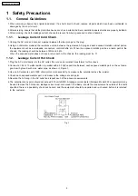
Definition of PCB Lead Free Solder being used
The letter of “PbF” is printed either foil side or components side on the PCB using the lead free solder.
(See right figure)
Service caution for repair work using Lead Free Solder (PbF)
·
The lead free solder has to be used when repairing the equipment for which the lead free solder is used.
(Definition: The letter of “PbF” is printed on the PCB using the lead free solder.)
·
To put lead free solder, it should be well molten and mixed with the original lead free solder.
·
Remove the remaining lead free solder on the PCB cleanly for soldering of the new IC.
·
Since the melting point of the lead free solder is higher than that of the normal lead solder, it takes the longer time to melt
the lead free solder.
·
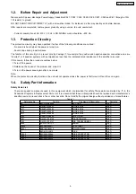
Use the soldering iron (more than 70W) equipped with the temperature control after setting the temperature at 350±30
degrees C (662±86°F).
Recommended Lead Free Solder (Service Parts Route.)
·
The following 3 types of lead free solder are available through the service parts route.
RFKZ03D01K-----------(0.3mm 100g Reel)
RFKZ06D01K-----------(0.6mm 100g Reel)
RFKZ10D01K-----------(1.0mm 100g Reel)
Note
* Ingredient: Tin (Sn), 96.5%, Silver (Ag) 3.0%, Copper (Cu) 0.5%, Cobalt (Co) / Germanium (Ge) 0.1 to 0.3%
9
SA-NS55E / SA-NS55EG
Summary of Contents for SA-NS55
Page 12: ...7 3 Disc Information 12 SA NS55E SA NS55EG ...
Page 19: ...9 3 Main Parts Location Diagram 19 SA NS55E SA NS55EG ...
Page 33: ...33 SA NS55E SA NS55EG ...
Page 37: ...10 2 Checking and Repairing of Panel P C B 37 SA NS55E SA NS55EG ...
Page 38: ...10 3 Checking and Repairing of Switch and Motor P C B 38 SA NS55E SA NS55EG ...
Page 39: ...10 4 Checking and Repairing Transformer P C B 39 SA NS55E SA NS55EG ...
Page 40: ...10 5 Checking and Repairing Power and AC Inlet P C B 40 SA NS55E SA NS55EG ...
Page 41: ...10 6 Checking and Repairing Main P C B 41 SA NS55E SA NS55EG ...
Page 42: ...10 7 Checking and Repairing CD Servo P C B 42 SA NS55E SA NS55EG ...
Page 50: ...SA NS55E SA NS55EG 50 ...
Page 54: ...SA NS55E SA NS55EG 54 ...
Page 56: ...56 SA NS55E SA NS55EG ...
Page 75: ...19 Exploded Views 19 1 Cabinet Parts Location Traverse Part Location SA NS55E SA NS55EG 75 ...
Page 76: ...SA NS55E SA NS55EG 76 ...
Page 77: ...19 2 Packaging SA NS55E SA NS55EG 77 ...
Page 78: ...SA NS55E SA NS55EG 78 ...


