


5.3. Using the VIERA Link “HDAVI Control™”
Using the VIERA Link "HDAVI Control
TM
"
What is
VIERA Link
TM
is a new name for EZ Sync
TM
.
VIERA Link "HDAVI Control" ?
VIERA Link "HDAVI Control" is a convenient function that offers linked operations of this unit, and
a P anasonic TV (VIERA) or DVD recor der (DIGA) under "HDAVI Control". You can use this function
by connecting the equipment with the HDMI cable . See the operating instructions f or connected
equipment for operational details.
VIERA Link "HDAVI Control", based on the control functions provided by HDMI which is an industry standard known as HDMI
CEC (Consumer Electronics Control), is a unique function that we have developed and added. As such, its operation with other
manufacturers’ equipment that supports HDMI CEC cannot be guaranteed.
This unit suppor ts "HDAVI Control 1" function.
This standard is compatible with Panasonic’s conventional HDAVI equipment.
Please refer to individual manuals for other manufacturers’ equipment supporting VIERA Link function.
1
You can select "Speaker Selection" ("Home Cinema" or "TV").
Home Cinema: This unit will be automatically turned on if it is in standby mode and the sound is from the speakers
connected to this unit.You can also adjust the volume level by using the volume control buttons.
TV: TV speakers are active.
2
When you switch off the TV (VIERA), this unit automatically turns off.
(This operation is unavailable when you set the input source as "FM ", "AM ", "CD " or "OPTION P. " on this unit.)
When VIERA Link "HDAVI Control" compatible recorder (DIGA) is connected with HDMI cable, the recorder (DIGA)
also turns off.
Note
When you operate the TV (VIERA) such as selecting a channel this units input selector will automatically switch to "TV ".
When you operate DVD recorder (DIGA), this unit's input selector will automatically switch to "DVD R.".
To operate other functions, use this units remote control.
What you can do with VIERA Link "HDAVI Control"
For correct use of VIERA Link "HDAVI Control"
Use TV (VIERA)'s remote control to select "Home Cinema" without turning on this unit (including the
remote control). (This unit is automatically turned on.)
Use the TV (VIERA)'s remote control to operate.
See TV (VIERA)'s operating instructions for details.
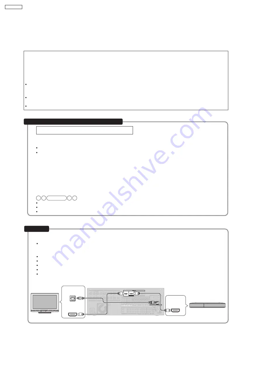
Connect your home theater equipment (VIERA Link "HDAVI Control" compatible VIERA television and DIGA DVD
recorder) with an HDMI cable.
It is recommended that you use Panasonic’s HDMI cable.
Recommended part number: RP-CDHG10 (1.0 m/3.3 ft.), RP-CDHG15 (1.5 m/4.9 ft.), RP-CDHG20 (2.0 m/6.6 ft.),
RP-CDHG30 (3.0 m/9.8 ft.), RP-CDHG50 (5.0 m/16.4 ft.), etc.
This unit incorporates HDMI (V .1.3 with Deep Color) technology.
Non-HDMI-compliant cables cannot be utilized.
Please use High Speed HDMI Cables that have the HDMI logo (as shown on the cover).
When outputting 1080p signal, please use the HDMI cables 5.0 meters (16.4 feet) or less.
You cannot enjoy TV sounds on this unit with only an HDMI cable. Connect TV to this unit with the optical fiber cable to
enjoy TV sound.
Connection
BI-WIRE
LF
HF
L
R
FRONT A
FRONT B
CENTER
SURROUND
SURROUND BACK
SPEAKERS
OUT
IN
IN
CD
BD/DVD PLAYER / ANALOG 8CH IN
DVD RECORDER
VCR
CABLE/SAT
GAME
TV
AUDIO
SURROUND BACK SURROUND
FRONT
SUBWOOFER
OUT
IN
IN
IN
(DVD RECORDER)
(BD/DVD PLAYER)
(CABLE/SAT)
HDMI 1
HDMI 2
HDMI 3
FRONT A
FRONT B
CENTER
SURROUND
SURROUND BACK
S VIDEO
COMPONENT VIDEO
L
R
IN
IN
IN
IN
AC IN~
OUT
IN
IN
OUT
OUT
IN
IN
IN
IN
TV MONITOR
TV MONITOR
DVD RECORDER
VCR
CABLE/SAT
GAME
DVD PLAYER
BD/
(BD/
DVD PLAYER)
(DVD RECORDER)
(CABLE/SAT)
1
2
3
DIGITAL IN
(DVD RECORDER) (BD/DVD PLAYER)
(TV)
(CD)
OPTICAL 1
OPTICAL 2
OPTICAL 3
COAXIAL
SUBWOOFER
Y
PB
PR
IN
OUT
OUT
IN
IN
IN
IN
TV MONITOR
DVD RECORDER
VCR
CABLE/SAT GAME
DVD PLAYER
BD/
(6-16 W EACH SPEAKER)
A OR B / BI-WIRE (4-16 W EACH SPEAKER) A AND B (6-16 W EACH SPEAKER)
OUT
CENTER
IN
IN
FM ANT
AM ANT
OPTION V 1
LOOP
EXT
DC OUT 5V
500mA MAX
75
W
R
L
R
R
L
L
LOOP ANT
GND
VIDEO
TV (VIERA)
Rear panel
HDMI IN
Digital audio
out (optical)
HDMI
OUT
D VD recorder
(DIGA)
12
SA-BX500PP
Summary of Contents for SA-BX500PP
Page 28: ...7 2 Main Components and P C B Locations 28 SA BX500PP ...
Page 64: ...SA BX500PP 64 ...
Page 82: ...82 SA BX500PP ...
Page 114: ...SA BX500PP 114 ...
Page 124: ...SA BX500PP 124 ...
Page 129: ...CN5501 Fig 3 Fan Connector 129 SA BX500PP ...
Page 134: ...SA BX500PP 134 ...
Page 136: ...136 SA BX500PP ...
Page 137: ...18 Exploded Views 18 1 Cabinet Parts Location SA BX500PP 137 ...
Page 138: ...SA BX500PP 138 ...
Page 139: ...SA BX500PP 139 ...
Page 140: ...18 2 Packaging SA BX500PP 140 ...


