33
9.3.
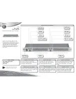
Disassembly of Top Cabinet
Step 1 Remove 2 screws on each side.
Step 2 Remove 5 screws.
Step 3 Slightly pull both side of Top Cabinet outwards as arrow
shown.
Step 4 Slightly lift up both side of Top Cabinet in an outward
direction as shown.
Step 5 Remove Top Cabinet.
Caution: During assembling, ensure that the Top Cabinet
catches are properly located into Front Panel Unit as
shown.
Summary of Contents for SA-AKX52
Page 13: ...13 5 Location of Controls and Components 5 1 Main Unit Key Button Operation ...
Page 14: ...14 5 2 Remote Control Key Button Operation ...
Page 32: ...32 9 2 Main Components and P C B Locations ...
Page 66: ...66 Step 9 Ground the 24P FFC with a short pin ...
Page 81: ...81 14 Simplified Block Diagram 14 1 Overall Simplified Block Diagram ...
Page 92: ...92 ...
Page 128: ...128 ...
Page 143: ...143 MMH1103 ...