13.2. Tuner Section
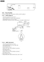
This section include details on the alignment of AM-IF and AM RF adjustment.
13.2.1. AM-IF Alignment
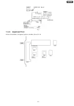
1. Set up the equipments as shown in Fig. 5.
2. Select [TUNER] mode on selector and set to [AM] mode.
3. Apply signal as shown in Fig. 5 from AM-SG.
4. Adjust Z2602 accordingly so that the output frequency is maximized at 450kHz in Fig. 6.
Fig. 5
Fig. 6
13.2.2. AM RF Adjustment
1. Set up the equipments as shown in Fig. 7.
2. Select [TUNER] on selector and set to [AM] mode.
3. Set AM-SG to 520kHz.
4. Receive 520kHz in the unit.
5. Adjust L2601 (OSC) so that the EVM-AC is maximized.
6. Set AM-SG to 600Hz.
7. Receive 600Hz in the unit.
8. Adjust L2601 (ANT) so that the EVM-SG is maximized.
9. Set AM-SG to 520kHz.
10. Receive 520kHz in the unit.
11. Adjust L2602 (OSC) so that the EVM-DC value is with 1.1±0.5V.
44
SA-AK640GCP
Summary of Contents for SA-AK640 GBP
Page 13: ...8 Operating Instructions Procedures 13 SA AK640GCP ...
Page 14: ...14 SA AK640GCP ...
Page 23: ...10 3 Main Parts Location 23 SA AK640GCP ...
Page 40: ...12 2 Checking and Repairing of Transformer P C B 40 SA AK640GCP ...
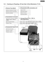
Page 41: ...12 3 Checking and Repairing of Panel Deck Deck Mechanism P C B 41 SA AK640GCP ...
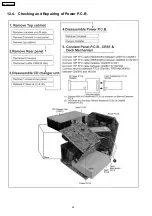
Page 42: ...12 4 Checking and Repairing of Power P C B 42 SA AK640GCP ...
Page 47: ...47 SA AK640GCP ...
Page 48: ...14 2 Power P C B Transformer P C B 48 SA AK640GCP ...
Page 49: ...14 3 Waveform Chart 49 SA AK640GCP ...
Page 50: ...50 SA AK640GCP ...
Page 52: ...52 SA AK640GCP ...
Page 58: ...58 SA AK640GCP ...
Page 60: ...SA AK640GCP 60 ...
Page 62: ...SA AK640GCP 62 ...
Page 68: ...SA AK640GCP 68 ...
Page 70: ...SA AK640GCP 70 ...
Page 76: ...SA AK640GCP 76 ...
Page 84: ...SA AK640GCP 84 ...
Page 89: ...21 Exploded Views 21 1 Cabinet Parts Location SA AK640GCP 89 ...
Page 90: ...SA AK640GCP 90 ...
Page 91: ...21 2 Deck Mechanism Parts Location RAA4502 S SA AK640GCP 91 ...
Page 92: ...21 3 Packaging SA AK640GCP 92 ...

