Panasonic RRQR80 - IC RECORDER, Service Manual
Introducing the Panasonic RRQR80 - IC RECORDER, a sleek and efficient device designed to capture and store high-quality audio recordings. Enhance your productivity with this versatile recorder, and ensure seamless functionality with our free, easily downloadable Service Manual. Access the manual today at manualshive.com to optimize your recording experience.
Share
Download


Reviews:
No comments
Related manuals for RRQR80 - IC RECORDER

LVC-9015G
Brand: LiteOn Pages: 41

Voice Tracer LFH0868
Brand: Philips Pages: 3

DPM-9300
Brand: Philips Pages: 56

Tiny16 A35
Brand: EDIC-mini Pages: 8

ICR-RS171NXSL
Brand: Sanyo Pages: 4

ICR-RS171NX
Brand: Sanyo Pages: 4

ICR-B180NX
Brand: Sanyo Pages: 6

ICR-FP550
Brand: Sanyo Pages: 25

ICR-B35
Brand: Sanyo Pages: 32

ICR-S240RM
Brand: Sanyo Pages: 42

ICR-B5000
Brand: Sanyo Pages: 38

ICR-B50 - 8 MB Digital Voice Recorder
Brand: Sanyo Pages: 37

ICR-NT300
Brand: Sanyo Pages: 44

ICR-FP600D - Digital MP3 Voice Recorder
Brand: Sanyo Pages: 55

ICR-B29
Brand: Sanyo Pages: 96
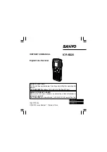
ICR-B220
Brand: Sanyo Pages: 89

ICR-EH800D - Xacti Digital Sound Recorder
Brand: Sanyo Pages: 138

ICR-1000
Brand: Sanyo Pages: 156


