


29
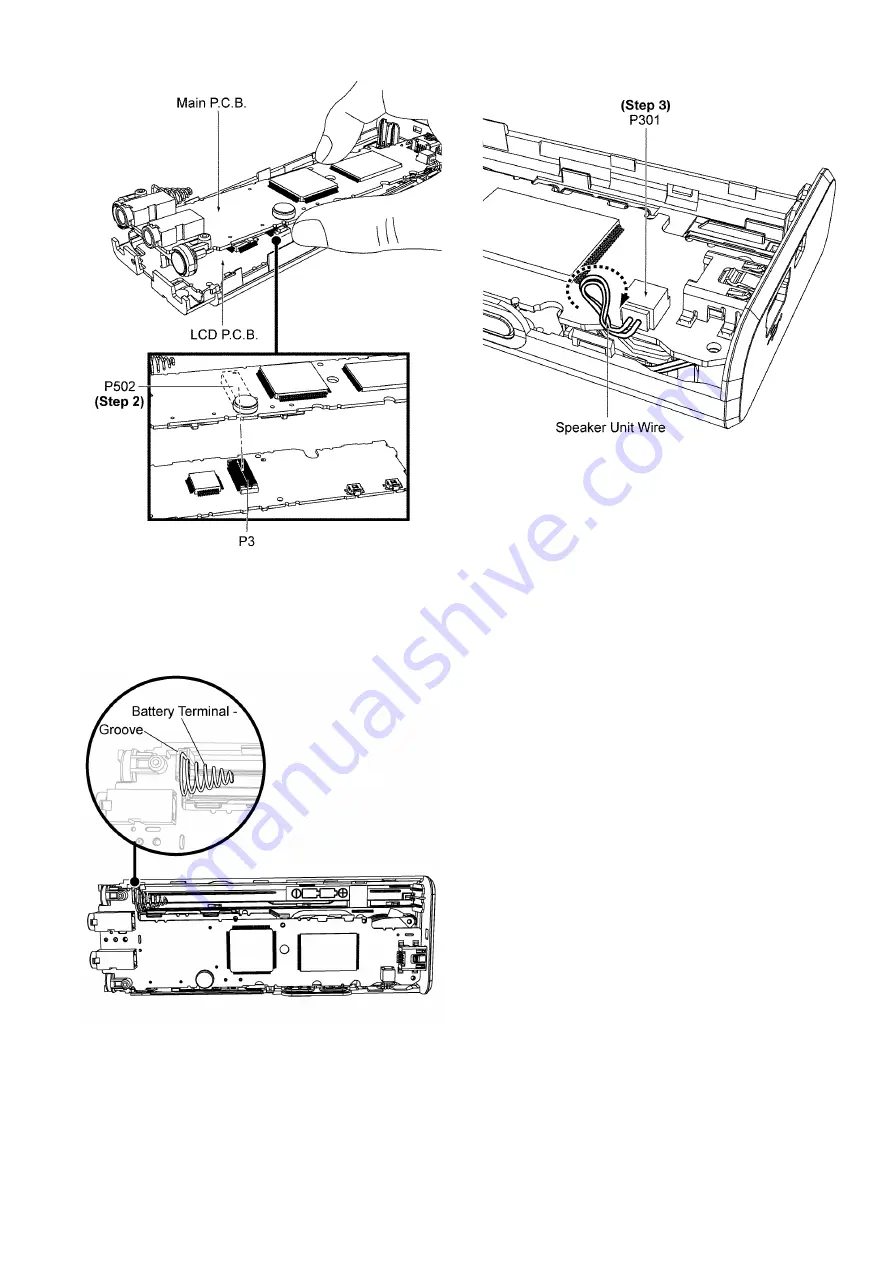
Step 2 :
Connect Main P.C.B. connector P502 to LCD P.C.B.
connector P3.
Caution 1 : Ensure the connectors are fully catched. A
“Click” sound will be heard.
Caution 2 : Ensure the Battery Terminal - is properly seated
into the groove.
Step 3 :
Connect the Speaker Unit Wire to connector P301 on
Main P.C.B.
Caution : Twist the Speaker Unit Wire one round in clock-
wise direction, press it down to the left side as shown.
Summary of Contents for RR-US570PP
Page 8: ...8 5 Location of Controls and Components 5 1 Components of IC Recorder ...
Page 9: ...9 5 2 Basic Operation ...
Page 14: ...14 7 Troubleshooting Guide ...
Page 15: ...15 ...
Page 16: ...16 ...
Page 18: ...18 8 1 Main Parts Location Diagram ...
Page 44: ...44 11 Illustration of IC s Transistors and Diodes C1AB00003086 120P RFKWNUS570 S RFKWNUS590 K ...