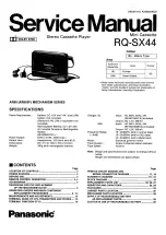
Page 1: ...nder license from Dolby Laboratories Licensing Corporation Dolby and the double D symbol are trademarks of Doiby Laboratories Licensing Corporation Charger E Input AC 220V 50Hz 4W RP BC155EY 0 include...
Page 2: ...R6 LR6 battery UM 3 or equiva lent not included into the battery case 2 Attach the battery case to the unit 3 Turn the screw until it locks To extend the playback time Install both types of battery re...
Page 3: ...op of the remote control earphone side for use In order to prevent the cord from being damaged do not slide the clip along the cord once it has been attached RQ SX44 Las meeda Cry CCrHOI To release To...
Page 4: ...es sound vigorous Set the VMSS selector to ON Raising the volume level using the VOLUME con trol on the main unit intensifies the VMSS effect eThe VOLUME control on the remote control can not be used...
Page 5: ...ON CHECKS AND MAIN COMPONENT REPLACEMENT PROCEDURES Mechanism block Fig 1 Fig 2 Note The adjustment of the mechanism block is unnecessary after replacement How to replace the head block The head and p...
Page 6: ...cement for the cassette lid A ass y and cassette lid B ass y esesrereecsceeccscccccccoccces B11 4 Replacement for the head block ass y and pinch roller arm eecccsssessceeccccccccsccccsoocccs 12 13 5 R...
Page 7: ...4 a ie He Short the short land Back side Gauge No E 3 Short the short land er Ss Back side Short the short land Back side 1 3 Gauge No E 3 Gauge No F 4 5 A Short the short land Short the short land Ba...
Page 8: ...hassis and install the belt between top of the motor and the coil P C B oe XQS14 A18FZ t Top of the motor Coil P C B Bottom of the motor Widening ey Chassis Sheet of non magenetic material 0 2mm 0 3mm...
Page 9: ...ion when installing Refer to above Fix with screws BB Link plate unit L R shaping Link plate unit L Tip of screw Holder plate Put the screw into the hole 0 RHQ0035 K Link plat it R Hold the link plate...
Page 10: ...n Casseite lid B ass y Groove Align the projection of link plate unit R with the groove of cassette lid B ass y Link plate unit R Cassette lid B ass y Move the link plate unit R in the direction of ar...
Page 11: ...FFC Pinch roller spring R fou pring R Pinch roller arm R Pinch roller spring U r RXLO005 t e Pinch roller arm L RXL0004 1 Head arm spring L Om RHD14008 K RHD14031 Assembly procedures for head block as...
Page 12: ...y t step 9 Tighten with screws RHD14008 K Align the switch bosses with the knobs Align the headphones jack with the hole of cabinet ass y Cassette lid ass y t step 5 Align the ribs with the holes and...
Page 13: ...d block De SED WQ _ _ Secure the screws 9 ae SS 5 Replacement for the intermediate ornament B intermediate ornament C and side ornament Follow GEap in item 1 on page 6 Remove the intermediate ornament...
Page 14: ...e five screws and PLAY STOP FF REW knob then remove the parts as shown left Operation P C B Intermediate ornament C RGK0665 H beckupk Use care that the zebra connector is not stick dust or grease Remo...
Page 15: ...ains set as the tape is rotating No pulse signal Stops or starts reverse playback as the tape has stopped rotating ie reached the end Tape turn control output terminal LED drive signal input Not used...
Page 16: ...ints of double faced foil patterns through holes on both side of the printed circuit board This printed circuit board diagram may be modified at any time with the development of new technology Mi SCHE...
Page 17: ...MO 0I5 Loch C203 L 8s 20 22 0 4V FWD R202 230 FN wo 150 2 5Vv33 0 8v PLAYBACK HEAD 1 preven 3 f 0 8v Rech 0 8V L 2 ca REV pmb to10 Nn id yl agt 9B 10 2 2 o 8v wag eee 6y X6 2S8815B87TX POWER SUPPLY MA...
Page 18: ...a inf Sers Nge sa Lid fe No Tas x x o ets mover x OF 2 Sx Sila Le orr re J on c ee Q303 R2 e0 mms 2SDIZ328STXRA SOLENOID DRIVE 7 TTT7tVOLUME C128 eoscco 4 c a 7 Zi TEST ES SHORT LAND 58 35 No tds 2 s...
Page 19: ...IBRATION BACH Q354 2 SDIBI9SSTX SWITCHING TOUCH SENSOR D303 MAI47TX Q355 356 2SDI819STX STABILIZER 28018 ISSTX lav SWITCHING TOUCH SENSOR Q362 365 33 SWITCHING UNSIIOTX vas Cees i tsie es a geal ae A...
Page 20: ...HANISM CONTROL LAW TEL TRANSISTOR S 28D1935 7TB iTRANSISTOR 2804983 67TB TRANSISTOR 28D1935 71TB 2804983 67TB 28D1935 7TB 2804983 677B Part Name Description vR2___JEVMAYSX50B23 TAPE SPEED ADJUSTMENT a...
Page 21: ...io aur aie enacevazen iow2 2K fooo nsec iow 4 7 a_i ine_a7 1 16R 2K R509 ERJSGEYJ223V 22K ec _eisxnav 20m finere ok p zo lennxiaeyinna 2k vi R205 ERJSGEYI229V 1 168 22K ERISGEYJ100V 1 16W R206 eee 3 9...
Page 22: ...ovosae av __10 ens asia 2 vse eee Mi REPLACEMENT PARTS LIST OT a a nc a SS CN a a a Ce A 0 CS CC Cc Cs CSOT PZ iene Isc in is Joe 7S Bonne earn core SS di deioa ee CCS SS C0 Ca 0 S eons func arewnrroo...
Page 23: ...lacement parts has been consolidated 2 Attach an original mechanism sheet covering the mechanism sheet already attached to the shared mechanism block Doubling doubling does not affect the unit s perfo...
Page 24: ...ply the specified grease to the areas marked xx as shown in the drawing Reine PartNo d The parts enclosed in the dotted boxes are supplied as a block assembly Therefore they are not supplied separatel...
Page 25: ...ry without Carrying Case e Replacement parts will be supplied for Carrying Case RFA0475 Q without Rechargeable Battery To your customers delivery Rechargeable Battery together with Carrying Case to pr...
Page 26: ...RFcO027 K CARRYING BAG Pee nee 0s hf o scese0 low ik Liwciiauiah 04D 0004 1 PINCH ROLLER ARM L AS RP BCLSSEBYA CHARGER EB A RKLOOOS PINCH ROLLER ARM R iy on a a aero amos oF as ede ee rT a SS ae es a...