background image

7

VCR

TIMER

A

M

Hi-Fi

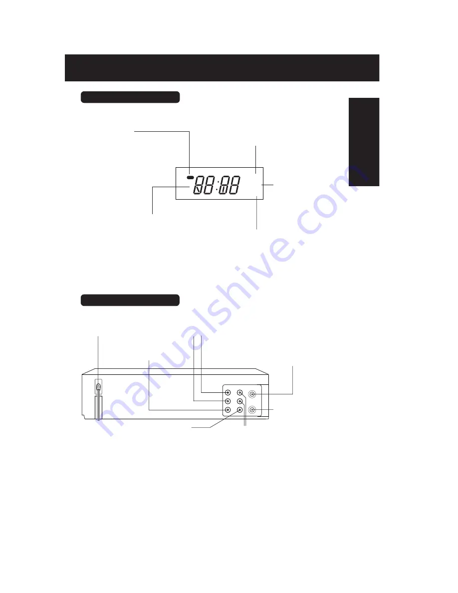
Rear View of the VCR

OUT

IN 1

OUT TO TV

VIDEO

AUDIO

IN FROM ANT.

     VHF/UHF

R

L

VHF/UHF Antenna
Input Terminal

VHF/UHF Antenna
Output Terminal

Video Output
 Connector

AC Power Plug

Audio Output
Connector (L/R)

Audio Input
Connector (L/R)

Video Input Connector

Hi-Fi Indicator
Lights up when Hi-Fi audio
is monitored in Playback
Mode.

VCR Indicator
Lights up when the
VCR/TV selector is
set to VCR.

Power Indicator
Lights up when power is on.

Clock/ Status/ Channel/ Speed Display
Displays the current time. Briefly displays VCR
status when a function button is pressed.
Briefly displays the channel number, or “L1” or
“L2” when a channel or line input is selected.
Briefly displays the recording speed when
SPEED is pressed.

Multi Function Display

Timer Indicator
Lights up when the VCR is set for Timer
Recording, or when One Touch Recording (OTR)
is used. Flashes when a Timer Recording is set,
but tape has not been inserted into the VCR

Initial Setup

(Connection)

Summary of Contents for PV-V462

Page 1: ...ORDER NO MKE0201001C1 B3 Video Cassette Recorder PV V462 PV V4602 PV V4622 PV V4612S PV V4022 K PV V4522 K PV V4612 K SPECIFICATIONS 2002 Matsushita Kotobuki Electronics Industries Ltd All rights...

Page 2: ...CR whose chassis is not isolated from the AC power line Use a transformer of adequate power rating as this protects the technician from accidents resulting in personalinjury from electrical shocks It...

Page 3: ...capacitor between each exposed metallic part on the set and a good earth ground as shown in figure 1 3 Use an AC voltmeter with 1 k V or more sensitivity to measure the potential across the resistor...

Page 4: ...place the assembly on a conductive surface such as aluminum foil to prevent electrostatic charge buildup or exposure of the assembly 3 Use only a grounded tip soldering iron to solder or unsolder ES d...

Page 5: ...e ground shall be connected to the grounding systemof the building as close to the point of cable entry as practical 3 OPERATION GUIDE 4 SERVICE NOTES PLEASE READ 4 1 SERVICE NOTES 4 1 1 SIMPLIFIED FA...

Page 6: ...Fig 1 4 Fig 1 5...

Page 7: ...a minute the VCR goes into VCR shut off condition Then the VCR stops and all VCR function buttons exceptfor power become non operational 3 Lock data will be cleared at the first power on operation af...

Page 8: ...l return to normal operation mode 4 1 3 EEPROM IC IC6005 MAIN C B A REPLACEMENT NOTE After replacing EEPROM IC IC6005 or Main C B A be sure to perform the PG SHIFTER ADJUSTMENT in ELECTRICAL ADJUSTMEN...

Page 9: ...rame Model Fig 3 2 2 Note 1 It is possible that the S Tab SW may not work correctly in Service Position 2 1 2 2 Recording can not be done In this case short the S Tab SW Pins on the foil side of the M...

Page 10: ...prevent accidental shock when servicing 4 1 6 SERVICE MODE In order to inhibit detection of the Supply Takeup Photo Transistors Reel Sensor and Cylinder Lock press and hold FF button and CH DOWN butt...

Page 11: ...tracking functions are not operational Fig 4 2 To release from this mode press PLAY or STOP button 4 1 8 CAUTION FOR INSTALLATION OF FRONT PANEL ASS Y CAUTION Opener Lever may be damaged when Front P...

Page 12: ...not use this method if Mechanism is jammed or locked Fig 6 1 4 1 9 2 Electrical Method Apply 10 0 V DC Power Supply to the Loading Motor terminals Loading DC to Portion a DC to Portion b Unloading DC...

Page 13: ...Arm Unit may be damaged or its spring may be out of place when the jammed tape is removed by force Remove a jammed tape as follows 4 1 10 1 Manual Method When a tape jam is encountered check the tape...

Page 14: ...e Up Ass y out far enough so that it clears the Drive Rack Arm slide the Drive Rack Unit as indicated by the arrow to remove the cassette tape from the Cassette Up Ass y 7 Check the cause of mechanica...

Page 15: ...C Power Supply be sure to cut the Motor Leads with a cutter etc Otherwise the Loading Motor Drive IC IC2501 may be damaged 2 If loading does not start in approx 2 seconds after DC Power Supply is appl...

Page 16: ...ed during the servicing of VCR whose chassis is not isolated from the AC power line Use a transformer of adequate power rating as this protects the technician from accidents resulting in personal inju...

Page 17: ...Figure...

Page 18: ...over Install the Top Cover front portion at a downward angle so that the tab on the Front Panel Ass y fits into the hole in the Top Cover Then lower the rear portion into place and tighten 2 Screws 44...

Page 19: ...operly Then press the Front Panel straight in Fig D1 3 Installation of Main C B A Mechanism Chassis onto the Frame When installing 2 Screws 460 slide the Holder Unit of the Cassette Up Ass y Refer to...

Page 20: ...Head Solder the Flat Cables Then install the Shield Plate as shown Fig D3 6 Installation of Cassette Up Ass y A Confirm that the Locking Tab under the Cassette Up Ass y is in Hole on the Mechanism Cha...

Page 21: ...C Hook Spring to the Drive Rack Arm on the Mechanism Chassis 5 2 MECHANISM SECTION 5 2 1 Disassembly Reassembly Method 5 2 2 Inner Parts Location Fig J1 1...

Page 22: ...5 2 3 EJECT Position Confirmation Fig J1 2...

Page 23: ...5 2 4 Full Erase Head and Cylinder Unit Fig J2 5 2 4 1 Reassembly Notes 1 After replacing the Cylinder Unit clear the Total elapsed Cylinder rotation time in hours to 0 Refer to USAGE SCREEN MODE in...

Page 24: ...gnment of Main Cam Gear Drive Rack Arm and Main Rod A Confirm that the hole on Main Rod is a Through Hole with a hole on chassis B Confirm that the hole on Drive Rack Arm is a Through Hole with a hole...

Page 25: ...Hole with a hole on chassis B Confirm that the hole on Intermediate Gear A is aligned with the hole on Lift Gear Fig J3 3 C Install the Intermediate Gear B so that the hole on the Intermediate Gear B...

Page 26: ...acement part 5 Installation of Main Cam Gear and Main Cam Push Nut A After installing the Support Angle install the Main Cam Push Nut with Needlenose Pliers etc so that it is flush with the chassis Th...

Page 27: ...Fig J4 1 5 2 6 1 Reassembly Notes 1 Installation of Center Clutch Unit A Fit the Center Clutch Unit into the Changing Gear Fig J4 2 5 2 7 Reel Gear Main Rod and SS Brake Arm Unit Fig J5 1...

Page 28: ...1 Alignment of Main Rod and T Loading Arm Unit A Align the Gear on T Loading Arm Unit with Gear of Main Rod Confirm that the Hole on Main Rod is a Through Hole with a hole on chassis Fig J5 2 5 2 8 C...

Page 29: ...ng Arm Unit and S Loading Arm Unit A Install the S Loading Arm Unit onto the chassis B Install the T Loading Arm Unit so that the hole on T Loading Arm Unit is aligned with the hole on S Loading Arm U...

Page 30: ...5 2 10 T Brake Unit Tension Control Arm Unit T Reel Table S Reel Table and Tension Arm Unit Fig J8 1 5 2 10 1 Reassembly Notes 1 How to distinguish between S Reel Table and T Reel Table Fig J8 2...

Page 31: ...5 2 11 Loading Post Base T Unit and Loading Post Base S Unit Fig J9 5 2 12 Opener Piece Drive Rack Arm Pinch Arm Unit P5 Arm Unit and Intermediate Gear A Fig J10 1...

Page 32: ...Arm Unit A Rotate the Lift Gear so that Hole A on Lift Gear is a Through Hole with a hole on chassis B Install the Intermediate Gear A so that the hole on Intermediate Gear A is aligned with the hole...

Page 33: ...5 2 13 Motor Block Unit Audio Control Head Unit Lift Gear Tension Arm Boss and Cleaner Arm Unit Fig J11 5 3 CASSETTE UP ASSEMBLY SECTION 5 3 1 Top Plate Wiper Arm Unit and Holder Unit Fig K1 1...

Page 34: ...t of Wiper Arm Unit and Drive Rack Unit A Slide the Drive Rack Unit to the far right as indicated by the arrow B Install the Wiper Arm Unit so that the hole on the Wiper Arm Unit is aligned with the h...

Page 35: ...ve on Side Plate L and R B Insert Holder Unit boss A and B into the grooves as shown in Fig K1 1 C Finally in the EJECT Position confirm that the protrudence on the Wiper Arm Unit is aligned with the...

Page 36: ...2 1 CLEANING PROCEDURE FOR THE UPPER CYLINDER UNIT 1 While slowly turning the Upper Cylinder Unit counterclockwise by hand gently rub the Video Heads with a Head Cleaning Stick VFK27 moistened with Et...

Page 37: ...oothly with a constant tension Symptom of Misadjustment 1 If the tape tension is less than the specified value the tape cannot come into proper contact with the Video Heads resulting in poor picture p...

Page 38: ...n Control Arm Unit Fig M2 2 Note 1 Be sure that the three probes of the meter are all in solid contact with the tape but not touching any other parts of the mechanism 2 It is recommended that measurem...

Page 39: ...r off condition The power comes on and the unit goes into service mode 3 Play back the alignment tape 4 To enter Tracking center mode press PLAY button in Play back mode TRACKING CENTER will be displa...

Page 40: ...ravels without curling at P2 and P3 posts Fig M3 3 8 To release from Tracking center mode press PLAY or STOP button 6 2 2 2 2 AUDIO CONTROL HEAD TILT ADJUSTMENT Purpose To confirm that the tape runs s...

Page 41: ...DJUSTMENT The height of the Audio Control Head replacement part is preset at the factory Purpose To be sure the tape runs properly along the Control Head Symptom of Misadjustment If the control signal...

Page 42: ...t the oscilloscope to the audio output jack on the rear side of the deck 2 Play back the 6 kHz Monaural Audio portion of the alignment tape 3 Adjust Black Screw C on the Audio Control Head base so tha...

Page 43: ...monitor 5 Connect the oscilloscope to TP3002 on the Video Signal Process Section of the Main C B A Use TP6205 as a trigger 6 Loosen the Black Screw D and tighten it slightly Set the H Position Adjust...

Page 44: ...e Range 0 001 V to 50 V Div Frequency Range DC to 50 MHz Probes 10 1 1 1 2 Isolation Transformer Variable 3 VHS Alignment Tape VFMS0003H6 4 TV monitor 6 3 3 HOW TO READ THE ADJUSTMENT PROCEDURES Fig E...

Page 45: ...wer comes on 2 Playback in SP mode Then press 100 button on the remote to enter EVR PG SHIFTER ADJUSTMENT mode PG ADJUSTMENT screen will appear on the TV Monitor Fig E2 1 3 Connect the channel 1 scope...

Page 46: ...n the remote control Then COMP will appear on the TV monitor and adjusted value will be written to Memory IC IC6005 Fig E2 3 6 Press STOP button on the remote control to release from EVR PG SHIFTER AD...

Page 47: ...MS 7 3 INTERCONNECTION SCHEMATIC DIAGRAM 7 4 SIGNAL WAVEFORMS 8 CIRCUIT BOARD LAYOUT 8 1 MAIN C B A 9 BLOCK DIAGRAMS 9 1 OVERALL BLOCK DIAGRAM Model PV V4022 K 9 2 OVERALL BLOCK DIAGRAM Models PV V452...

Page 48: ...C7010 R3875 TP3805 IC3801 Q3001 IC4151 Q4151 Q3875 C3820 TP6007 TP4202 R4209 Q4007 Q4005 Q4004 P4001 Q4006 IC4201 R4213 R4225 R4224 R4214 R4013 R7004 R4218 C4216 R4210 C4225 C4915 C4911 C4213 C4226 C4...

Page 49: ...LP SLP R HEAD VIDEO SP R HEAD VIDEO SP L HEAD MODE SELECT SWITCH SW6002 P3501 PIN PIN PB AUDIO SIGNAL REC AUDIO SIGNAL PB VIDEO SIGNAL REC VIDEO SIGNAL VIDEO AUDIO VIDEO AUDIO VIDEO BLACK DET L SEGME...

Page 50: ...DISPLAY WITH FIP VIDEO LP SLP L HEAD VIDEO LP SLP R HEAD Hi Fi AUDIO L HEAD Hi Fi AUDIO R HEAD VIDEO SP R HEAD VIDEO SP L HEAD I2C CONTROL MODE SELECT SWITCH SW6002 P3501 PIN PB AUDIO SIGNAL REC AUDI...

Page 51: ...nd the connection between associated connectors Example The connections between C B A s are shown below POWER SUPPLY C B A MAIN C B A The Number of pins of the Connector Connector No on Main C B A P15...

Page 52: ...M1 CAP PWM0 CYL PANE_CLK LED_K DVDD OSC_OUT OSC_IN 14MHz DVSS KEY12 KEY13 SXI NC NC NC CV_OUT OSD_VSS CV_IN CV_IN2 OSD_VDD AFCC AFCLPF PANE_CS 3CH_HIZ 4CH_L NC BLACK_H NC CATV_CLK NC NC NC NC NC NC NC...

Page 53: ...V SS L FGF CAP FG CAP FG AFG VRO V REF 1 VRI V REF 2 AVSS VSS CTLA CTL AMP AVDD VDD RCTLP CTL PULSE RCTLN CTL PULSE CO PB CONTROL PULSE NC Not used NC Not used T PHOTO_L S PHOTO_L TAKEUP PHOTO TR L SU...

Page 54: ...209 Q3201 Q3202 C3220 C3219 L3203 C3218 R3206 TP3401 C3515 C3518 C3519 C3102 D3008 C3023 C3022 C3051 C3050 TP3004 C3036 L3016 C3030 TP3010 R3042 TP3005 C3049 R3007 R3006 R3041 R3010 R4151 C4152 C4151...

Page 55: ...EE VV EE MAIN DE EMPHASIS Y C MIX GCA DET CLAMP LPF GCA MUTE Y C MIX CLAMP ARTFICIAL V H SYNC MIX EE VV ATT ATT ATT TUNER LINE 1 LINE 2 AGC DET SYNC SEPARATION I2C BUS VXO X2 BPF 2FSC FSC ATT COMPONEN...

Page 56: ...1 Q14 22 Q8 15 Q9 16 Q10 17 Q11 18 PGND 19 Q12 20 Q4 11 Q5 12 Q15 23 ENB 24 Q6 13 Q7 14 ENA 25 SOUT 26 27 RC 28 Vcc SW6317 EVQ11A09K SW6312 EVQ11A09K SW6313 EVQ11A09K SW6314 EVQ11A09K SW6315 EVQ11A09K...

Page 57: ...015 C4211 0 015 C4212 TP4208 PT C4917 0 1 C4918 0 1 C4919 0 1 C4920 0 022 C4921 PT R4456 PT 3R3 50V C4903 PT TP4205 1500 R4226 C4234 PT R4228 10K C4229 0 01 R4227 PT C4914 PT R4903 PT L4902 WA5 TP4203...

Page 58: ...0 47 50V C1051 MA4110N HTA D1051 3900 R1008 WA7 5 TP1001 18mH L1001 2SC4533LP KT G 2SC4559LP KT Q1001 C1080 330 35V 100 6 3V C1058 R1082 10K 82 200V C1004 33K 2W R1004 0 01 C1001 R1056 PT ERA18 04 D10...

Page 59: ...TP3806 PT TP3807 PT C3830 0 056 AN3275 IC3801 1 2 3 4 5 6 7 8 9 10 27 28 29 30 31 32 33 34 35 36 19 20 21 22 23 24 25 26 11 12 13 14 15 16 17 18 0 47 50V C3826 R3823 PT R3824 PT R3825 PT R3826 PT R38...

Page 60: ...ECEIVER UNIT UHF VHF TUNER TV DEMODULATOR UNIT UHF VHF IN UHF VHF OUT AUDIO OUT R CH AUDIO IN 1 R CH 23 Pins PIN PIN AC CORD 1 2 AC120V P3501 P3501 P3502 FRAME GND P4002 P4002 AUDIO CONTROL FULL ERASE...

Page 61: ...LK LED_K DVDD OSC_OUT OSC_IN 14MHz DVSS KEY12 KEY13 SXI NC NC NC CV_OUT OSD_VSS CV_IN CV_IN2 OSD_VDD AFCC AFCLPF PANE_CS 3CH_HIZ 4CH_L NC BLACK_H NC CATV_CLK NC NC NC NC NC NC NC PFG C R SS_L FGF AFG...

Page 62: ...LK LED_K DVDD OSC_OUT OSC_IN 14MHz DVSS KEY12 KEY13 SXI NC NC NC CV_OUT OSD_VSS CV_IN CV_IN2 OSD_VDD AFCC AFCLPF PANE_CS 3CH_HIZ 4CH_L NC BLACK_H NC CATV_CLK NC NC NC NC NC NC NC PFG C R SS_L FGF AFG...

Page 63: ...218 R3206 TP3401 C3515 C3518 C3519 C3102 D3008 C3023 C3022 C3051 C3050 TP3004 C3036 L3016 C3030 TP3010 R3042 TP3005 C3049 R3007 R3006 R3041 R3010 R4151 C4152 C4151 C4153 R4153 R4154 Q4151 R4161 R4155...

Page 64: ...218 R3206 TP3401 C3515 C3518 C3519 C3102 D3008 C3023 C3022 C3051 C3050 TP3004 C3036 L3016 C3030 TP3010 R3042 TP3005 C3049 R3007 R3006 R3041 R3010 R4151 C4152 C4151 C4153 R4153 R4154 Q4151 R4161 R4155...

Page 65: ...GND 19 Q12 20 Q4 11 Q5 12 Q15 23 ENB 24 Q6 13 Q7 14 ENA 25 SOUT 26 27 RC 28 Vcc SW6317 EVQ11A09K SW6312 EVQ11A09K SW6313 EVQ11A09K SW6314 EVQ11A09K SW6315 EVQ11A09K SW6307 EVQ11A09K SW6308 EVQ11A09K S...

Page 66: ...GND 19 Q12 20 Q4 11 Q5 12 Q15 23 ENB 24 Q6 13 Q7 14 ENA 25 SOUT 26 27 RC 28 Vcc SW6317 EVQ11A09K SW6312 EVQ11A09K SW6313 EVQ11A09K SW6314 EVQ11A09K SW6315 EVQ11A09K SW6307 EVQ11A09K SW6308 EVQ11A09K S...

Page 67: ...7 0 1 C4918 0 1 C4919 0 1 C4920 0 022 C4921 PT R4456 PT 3R3 50V C4903 PT TP4205 1500 R4226 C4234 PT R4228 10K C4229 0 01 R4227 PT C4914 PT R4903 PT L4902 WA5 TP4203 PT 10K R4223 D4210 WA5 D4205 PT D42...

Page 68: ...7 0 1 C4918 0 1 C4919 0 1 C4920 0 022 C4921 PT R4456 PT 3R3 50V C4903 PT TP4205 1500 R4226 C4234 PT R4228 10K C4229 0 01 R4227 PT C4914 PT R4903 PT L4902 WA5 TP4203 PT 10K R4223 D4210 WA5 D4205 PT D42...

Page 69: ...0 R1008 WA7 5 TP1001 18mH L1001 2SC4533LP KT G 2SC4559LP KT Q1001 C1080 330 35V 100 6 3V C1058 R1082 10K 82 200V C1004 33K 2W R1004 0 01 C1001 R1056 PT ERA18 04 D1002 TP1002 PT 10 16V C1052 100P C1029...

Page 70: ...0 R1008 WA7 5 TP1001 18mH L1001 2SC4533LP KT G 2SC4559LP KT Q1001 C1080 330 35V 100 6 3V C1058 R1082 10K 82 200V C1004 33K 2W R1004 0 01 C1001 R1056 PT ERA18 04 D1002 TP1002 PT 10 16V C1052 100P C1029...

Page 71: ...275 IC3801 1 2 3 4 5 6 7 8 9 10 27 28 29 30 31 32 33 34 35 36 19 20 21 22 23 24 25 26 11 12 13 14 15 16 17 18 0 47 50V C3826 R3823 PT R3824 PT R3825 PT R3826 PT R3827 PT R3828 PT SW_5V_VIDEO 18 BLACK...

Page 72: ...275 IC3801 1 2 3 4 5 6 7 8 9 10 27 28 29 30 31 32 33 34 35 36 19 20 21 22 23 24 25 26 11 12 13 14 15 16 17 18 0 47 50V C3826 R3823 PT R3824 PT R3825 PT R3826 PT R3827 PT R3828 PT SW_5V_VIDEO 18 BLACK...

Page 73: ...VHF TUNER TV DEMODULATOR UNIT UHF VHF IN UHF VHF OUT AUDIO OUT R CH AUDIO IN 1 R CH 23 Pins PIN PIN AC CORD 1 2 AC120V P3501 P3501 P3502 FRAME GND P4002 P4002 AUDIO CONTROL FULL ERASE HEAD UNIT P4092...

Page 74: ...VHF TUNER TV DEMODULATOR UNIT UHF VHF IN UHF VHF OUT AUDIO OUT R CH AUDIO IN 1 R CH 23 Pins PIN PIN AC CORD 1 2 AC120V P3501 P3501 P3502 FRAME GND P4002 P4002 AUDIO CONTROL FULL ERASE HEAD UNIT P4092...

Page 75: ...ncluida As an ENERGY STAR Partner Matsushita Electric Corporation of America has determined that this product or product model meets the ENERGY STAR guidelines for energy efficiency VCR Plus ALLSET an...

Page 76: ...or outdoors or before leaving the unit unused for extended periods of time disconnect all equipment from the power source as well as the antenna and cable system 4 WHEN THE UNIT IS PLUGGED IN Never e...

Page 77: ...rns the user that uninsulated voltage within the unit may have sufficient magnitude to cause electric shock Therefore it is dangerous to make any kind of contact with any inside part of this unit This...

Page 78: ...5368 Date of Purchase Dealer Purchased From Dealer Address Dealer Phone No Model No PV V4622 Serial No Prevent Accidental Tape Erasure Record Tab Screw driver Cover the hole with cellophane tape To re...

Page 79: ...over Important Safeguards and Precautions 2 3 Accessories 4 Loading the Batteries 4 Prevent Accidental Tape Erasure 4 Record Playback Time 4 Location of Controls 6 7 Initial Setup for ANT Cable VCR TV...

Page 80: ...Play and Slow mode PLAY Plays a tape FAST FORWARD SEARCH Fast forwards tape forward visual search REWIND SEARCH Rewinds tape reverse visual search STOP Stops tape SAP Hi Fi Selects audio mode for play...

Page 81: ...R TV selector is set to VCR Power Indicator Lights up when power is on Clock Status Channel Speed Display Displays the current time Briefly displays VCR status when a function button is pressed Briefl...

Page 82: ...wall outlet VCR comes on and auto channel and clock set starts If screen right does not appear check VCR TV connection and if TV is tuned to channel 3 try switching it to channel 4 To change VCR s out...

Page 83: ...CONNECTION screen is displayed Press to select connection VCR TV or VCR CABLE DSS BOX TV and press to set 4 Press ACTION on remote to display CLOCK screen Manual Clock Set Press to select the month a...

Page 84: ...ABLE Cable TV Converter Box 1 Turn TV on and tune to channel 3 Plug VCR Power Cord into AC wall outlet VCR comes on and auto channel and clock set starts If screen right does not appear check VCR TV c...

Page 85: ...ss ACTION on remote to display CLOCK screen Manual Clock Set Press to select the month and to set In the same manner select and set the date year time and DST daylight saving time Press ACTION to star...

Page 86: ...Y OFF CABLE DSS BOX SET UP VCR Plus CH SET UP VCR C A CLOCK CHANNEL SELECT EXIT ACT I ON Channels 1 Press to select CHANNEL 2 Press to select ANTENNA then press to set your antenna system TV or CABLE...

Page 87: ...3 Press ACTION TIME ZONE ADJUST returns to 0 if clock is set manually and press to subtract or add hour s as necessary Add or Delete a Channel To add channel Select channel with NUMBER keys and press...

Page 88: ...r eject tape PLAY Ready Checklist All connections are made p 8 10 24 TV and VCR are plugged in TV is on and tuned to CH3 4 or VIDEO Remote is in VCR mode Press VCR Forward Reverse scene search Press F...

Page 89: ...on Multi Function Display select channels at TV recording continues Select channels at VCR Other channels cannot be viewed during recording press VCR TV VCR lights up on Multi Function Display select...

Page 90: ...nd VCR plugged in and turned on VCR TV selector set to VCR Clock set correctly Tape has rec tab p 4 Remote is in VCR mode Press VCR Press PROG VCR button again to exit To Enter More Programs press to...

Page 91: ...10 SP SU 9 00P 10 00P L1 LP 1 2 3 4 1 Press PROG VCR button 2 Press to select LIST To cancel a Timer Recording in progress 1 Press to display 2 Repeat Step 3 p 16 to set new programs Press PROG VCR b...

Page 92: ...e each entry within 1 minute or VCR will leave this mode Once local channels have been programmed they will stay in memory even in the case of a power failure If the start time for a timer recording c...

Page 93: ...s System Channel Setup Part 1 section on page 18 If you selected SELECT VCR Plus CH perform steps 2 3 in the Auto VCR Plus System Channel Setup Part 2 section on this page Press ACTION to return to no...

Page 94: ...ON VCR C A CLOCK CHANNEL SELECT EXIT ACT I ON REPEAT PLAY OFF TIME STAMP ON REMOTE WARNING ON AUTO SHUT OFF OFF AUTO VCR TV ON IDIOMA LANGUE ENGLISH VCR S OUTPUT CH 3 VCR C A CLOCK CH CLEAR ADD DLT SE...

Page 95: ...annel setup is done channels stay in memory If a power interruption occurs VCR Plus channel setup may be lost Please do VCR Plus channel setup again Obtain unlisted PlusCode numbers by calling 1 900 4...

Page 96: ...every TV cable box or DSS made by the manufacturer listed If you get no response your particular unit cannot be controlled There are NO additional codes for the products listed If your product is not...

Page 97: ...itachi 31 Jerrold 01 84 83 34 03 02 04 55 65 66 67 68 120 106 121 122 115 117 118 124 Jasco 30 04 124 Macom 31 Magnavox 26 112 Matsushita 17 16 08 87 109 Movietime 32 39 42 44 126 38 40 Maestro 74 35...

Page 98: ...N terminals you can connect your VCR to them to receive higher quality picture and sound IN VIDEO AUDIO R L OUT IN FROM ANT OUT TO TV AUDIO IN1 VHF UHF R L VIDEO OUT TV IN 2 IN 1 CABLE BOX OUT IN OUT2...

Page 99: ...ack with true stereo sound Standard stereo tapes will playback in monaural sound To listen to Hi Fi stereo playback the VCR AUDIO L R jacks must be connected to a stereo TV or an external stereo amp a...

Page 100: ...FF REW SELECT SET ACTION detects and marks the beginning and end points of commercials on your tape for recordings over 15 minutes in length When marked tape is played back the VCR a automatically adv...

Page 101: ...es during the program To view the portion of tape being incorrectly skipped press PLAY while the VCR is skipping reverse the tape to a point just prior to where the skipping began and press PLAY again...

Page 102: ...inished Yes By setting the C A PLAYBACK to MANUAL see page 27 you can view or advance through commercials as desired Yes works in SP LP and SLP Yes As long as C A PLAYBACK is set to AUTO see page 27 t...

Page 103: ...he start of the detected preview While the tape is reversing back if SEARCH M A SKIP is pressed will begin searching for the next preview While searching for the next preview if you see the start of a...

Page 104: ...pon locating end point If Program End Search is started very close to an index mark that mark may be skipped over SEARCH INDEX PROG END MOVIE SEARCH START FF NEXT SEARCH M A SKIP EXIT STOP Fig 1 Progr...

Page 105: ...ition to reset to 0 00 00 Continue to record playback etc Press STOP Unit will go into FF or REW mode and stop at the last point the Counter was set to 0 00 00 Press CA ZERO in Stop mode to start ZERO...

Page 106: ...r 10 manually created captions You need a list of stations and the channel numbers you receive them on To make corrections Press and to select the channel number then press to change or ADD DLT to del...

Page 107: ...r if invalid key is pressed Press ACTION to return to normal screen VCR C A CLOCK CH SELECT SET EXIT ACT I ON REPEAT PLAY OFF TIME STAMP ON REMOTE WARNING ON AUTO SHUT OFF ON AUTO VCR TV ON IDIOMA LAN...

Page 108: ...3 2 1 SELECT EXIT ACT I ON REPEAT PLAY OFF TIME STAMP ON REMOTE WARNING ON AUTO SHUT OFF OFF AUTO VCR TV ON IDIOMA LANGUE ENGLISH VCR S OUTPUT CH 3 VCR C A CLOCK CH Press ACTION to display menu VCR C...

Page 109: ...l not function during Play or Record Note When set to ON picture is displayed regardless of signal strength ON Picture is displayed despite signal condition an may have poor quality OFF Screen turns s...

Page 110: ...e done on both playing and recording VCRs at the same time VCR IN FROM ANT OUT TO TV VIDEO OUT AUDIO OUT AUDIO IN VCR VIDEO IN TV VHF UHF R L R L R L R 1 2 Front of VCR Audio Video In Terminals on the...

Page 111: ...late more dust We recommend using a nonabrasive antistatic cleaner and polisher Cleaning the VCR Note Designs and specifications are subject to change without notice V I DEO HEADS MAY NEED CLEAN I NG...

Page 112: ...AD CLEANING CASSETTE OR REFER TO MANUAL END PLAY VCR LOCK ACTIVATED 33 REC 12 00AM 0 25 ABC 0 12 34 SP STEREO SAP MONO VCR Status Clock Displays Function Channel Displays Blank Tape No Video Signal In...

Page 113: ...Check connections between VCR external antenna and TV Press VCR button for VCR mode P 22 Check Remote batteries P 4 Correction Check connections between VCR external antenna and TV Check channel selec...

Page 114: ...ies are not warranted Tape if included New video tape in exchange for defective video tape for five 5 days For assistance in the continental U S A in obtaining repairs please ship the product to Panas...

Page 115: ...THE WARRANTY ALL EXPRESS AND IMPLIED WARRANTIES INCLUDING THE WARRANTIES OF MERCHANTABILITY AND FITNESS FOR PARTICULAR PURPOSE ARE LIMITED TO THE APPLICABLE WARRANTY PERIOD SET FORTH ABOVE Some states...

Page 116: ...EL RELOJ ES INCOMPLETO aparece coloque manualmente el tiempo vealo abajo FIJACION AUTOMATICA DEL RELOJ ES INCOMPLETO POR FAVOR FIJE EL RELOJ CON LA TECLA ACTION VCR C A RELOJ CANAL Selecciones se real...

Page 117: ...presione para seleccionar y presione para ajustar los tiempos de INICIO PARADA CANAL o entrada de L NEA p g 36 CATEGORIA y velocidad del cassette SP LP SLP Categor a NO DEPORTE CINE COMEDIA MUSICA DR...

Page 118: ...on Channel Displays 38 H Head Cleaning 37 Hi Fi Indicator 7 I Important Safeguards and Precautions 2 Index Search 30 Initial Setup 8 9 10 11 L Limited Warranty 40 41 M Manual VCR Plus System Channel S...

Page 119: ...C PB WF12 52 0mVp p V1 PIN 55 OF IC3001 20mV 0 5ms1 PB WF13 V1 5 2Vp p PIN 93 OF IC3001 2V 2ms 1 CUE REV SLOW STILL WF14 0 24Vp p V1 PIN 31 OF IC3001 0 1V 5ms 2 REC WF15 0 35 Vp p V1 PIN 31 OF IC3001...

Page 120: ...5 OF T1001 5V 2 s1 POWER ON WF27 V1 PIN 8 OF T1001 10V 2 s1 POWER ON 40Vp p WF29 15 0Vp p V1 PIN 11 OF T1001 5V 2 s1 POWER ON WF30 0 23Vp p V1 BASE OF Q1002 0 1V 2 s1 POWER ON WF31 5 00Vp p V1 PIN 27...

Page 121: ...10 2 MECHANISM BOTTOM SECTION...

Page 122: ...10 3 CASSETTE UP COMPARTMENT SECTION...

Page 123: ...10 4 CHASSIS FRAME AND CASING PARTS SECTION...

Page 124: ...10 5 PACKING PARTS AND ACCESSORIES SECTION...

Page 125: ...EMENT PARTS LISTS BEFORE REPLACING PARTS READ THE FOLLOWING 11 1 REPLACEMENT NOTES 11 1 1 General Notes 1 Use only original replacement parts To maintain original function and reliability of repaired...

Page 126: ...o the parts list 5 Parts different in shape or size may be used However only interchangeable parts will be supplied as service replacement parts 6 All of parts are supplied from MKI 7 Item numbers wit...

Page 127: ...Unit Ref No 123 replacement part is available as a complete assembly unit only Do not try to disassemble the Infrared Remote Control Unit However the battery cover is available separately as areplace...

Page 128: ...fter replacing EEP ROM IC IC6005 or MAIN C B A be sure to perform the PG SHIFTER ADJUSTMENT in ELECTRICAL ADJUSTMENT procedures 6 Microcontroller IC IC6001 and EEP ROM IC IC6005 replacement note for P...

Page 129: ...CYLINDER UNIT B C D E F G 1 12 VEHS0596 AUDIO CONTROL ERASE HEAD UNIT A G 1 12 VEHS0598 AUDIO CONTROL ERASE HEAD UNIT B C D E F 1 14 LSDG0112 LIFT GEAR 1 16 VXDS0213 LOADING POST BASE S UNIT 1 17 VXDS...

Page 130: ...IT 3 71 VYPS7118 FRONT PANEL ASS Y A 4 71 VYPS7117 FRONT PANEL ASS Y B 4 71 VYPS7138 FRONT PANEL ASS Y C 4 71 VYPS7137 FRONT PANEL ASS Y D 4 71 VYPS7139 FRONT PANEL ASS7Y E 4 71 VYPS7115 FRONT PANEL A...

Page 131: ...SC0425 GROUNDING PLATE 4 270 LSSC0426 GROUNDING PLATE 4 271 LSGQ0041 CUSHION PLASTIC C D E F G 4 401 VHDS0475 SCREW STEEL 1 410 VHDS0498 SCREW W WASHER STEEL 1 414 VHNS0070 MAIN CAM PUSH NUT STEEL 2 4...

Page 132: ...USTMENT DRIVER 11 3 ELECTRICAL REPLACEMENT PARTS LIST PRINTED CIRCUIT BOARD ASSEMBLY Ref No Part No Part Name Description Remarks E10 LSEP2006GA MAIN C B A A E S D RTL E10 LSEP2006HA MAIN C B A B E S...

Page 133: ...5 KS24C011CS IC 1K EEP ROM See Replacement Note E S D IC6005 AT24C01A10SI IC 1K EEP ROM See Replacement Note E S D IC6005 C0ZBZ0000015 IC 1K EEP ROM See Replacement Note E S D IC6005 C3EBCC000038 IC 1...

Page 134: ...P Q4101 B1ABCF000011 TRANSISTOR SI NPN CHIP Q4151 UNR521200L TRANSISTOR SI NPN CHIP A Q4151 B1GBCFLL0012 TRANSISTOR SI NPN CHIP A Q4151 MUN5212T1 TRANSISTOR SI NPN CHIP A Q6001 2SD1819A RS TRANSISTOR...

Page 135: ...SI D1009 B0JCMD000014 DIODE SI D1009 MA2YD2300L DIODE SI D1009 SFPJ 53 DIODE SI D1015 MA2180LA DIODE ZENER 18V D1015 1N4746A T DIODE ZENER 18V D1015 1N4746ARL DIODE ZENER 18V D1016 MA2C165001VT DIODE...

Page 136: ...1 4W 330 R1058 ERDS2TJ104 CARBON 1 4W 100K R1080 ERDS2TJ103 CARBON 1 4W 10K G R1081 ERJ6GEYJ102V MGF CHIP 1 10W 1K G R1082 ERJ6GEYJ103V MGF CHIP 1 10W 10K G R1083 D0AF122JA038 CARBON 1 2W 1 2K G R3001...

Page 137: ...F CHIP 1 10W 5 6K A R4028 ERJ6GEY0R00V MGF CHIP 1 10W 0 R4102 ERJ6GEYJ333V MGF CHIP 1 10W 33K R4103 ERJ6GEYJ153V MGF CHIP 1 10W 15K R4151 ERJ6GEYJ101V MGF CHIP 1 10W 100 A R4152 ERJ6GEYJ101V MGF CHIP...

Page 138: ...J472V MGF CHIP 1 10W 4 7K R6057 ERJ6GEYJ102V MGF CHIP 1 10W 1K R6059 ERJ6GEYJ102V MGF CHIP 1 10W 1K R6060 ERJ6GEYJ105V MGF CHIP 1 10W 1M A B C E F R6060 ERJ6GEYJ475V MGF CHIP 1 10W 4 7M D G R6062 ERJ6...

Page 139: ...3 9K R6321 ERJ6GEYJ123V MGF CHIP 1 10W 12K R6521 ERJ6GEYJ103V MGF CHIP 1 10W 10K R7001 ERJ6GEYJ473V MGF CHIP 1 10W 47K A CAPACITORS Ref No Part No Part Name Description Remarks C1001 ECKATS103MF CERA...

Page 140: ...IC 35V 330UF G C3001 ECA0JM471 ELECTROLYTIC 6 3V 470UF C3003 ECEA1CKA470 ELECTROLYTIC 16V 47UF C3004 ECJ2VF1E104Z C CHIP 25V 0 1UF C3014 ECJ2VF1E104Z C CHIP 25V 0 1UF C3015 ECJ2VF1E104Z C CHIP 25V 0 1...

Page 141: ...504 ECJ2VF1E104Z C CHIP 25V 0 1UF C3505 ECJ2VF1E104Z C CHIP 25V 0 1UF C3506 ECJ2VF1E104Z C CHIP 25V 0 1UF C3507 ECJ2VF1E104Z C CHIP 25V 0 1UF C3508 ECJ2VF1E104Z C CHIP 25V 0 1UF C3514 ECEA0JKA101 ELEC...

Page 142: ...CHIP 25V 0 1UF A C4201 ECEA1EKA4R7 ELECTROLYTIC 25V 4 7UF B C D E F G C4202 ECEA1EKA4R7 ELECTROLYTIC 25V 4 7UF B C D E F G C4203 ECEA0JKA330 ELECTROLYTIC 6 3V 33UF B C D E F G C4204 ECEA0JKA330 ELECTR...

Page 143: ...30UF D G C6019 ECEA1CKA100 ELECTROLYTIC 16V 10UF A B C E F C6019 ECA0JM101B ELECTROLYTIC 6 3V 100UF D G C6021 ECJ2VF1H103Z C CHIP 50V 0 01UF C6024 ECJ2VC1H101J C CHIP 50V 100PF G C6026 ECJ2VB1H102K C...

Page 144: ...ESN101KA COIL 100UH E F G L3802 ELESN470KA COIL 47UH E F G L4001 ELELN153KA COIL 15MH L4002 ELESN101KA COIL 100UH L4101 ELESN471KA COIL 470UH L4201 ELESN101KA COIL 100UH B C D E F G L4451 ELESN101KA C...

Page 145: ...AB0003 FUSE 125V 1 6A F1001 K5D162AQ0004 FUSE 125V 1 6A F1001 K5D162ADA001 FUSE 125V 1 6A PR1001 UNH000600A IC PROTECTOR 1 5A PR1001 B1ZAZ0000040 IC PROTECTOR 1 5A PR1001 LSSF009A25E IC PROTECTOR 1 5A...

Page 146: ...ISCELLANEOUS Ref No Part No Part Name Description Remarks 711 LSSZ0004 INFRARED RECEIVER UNIT 716 B3CKS0000001 LED DISPLAY PANEL 741 LSJA0360 AC CORD W PLUG AC 120V 741 LSJA0358 AC CORD W PLUG AC 120V...

Reviews: