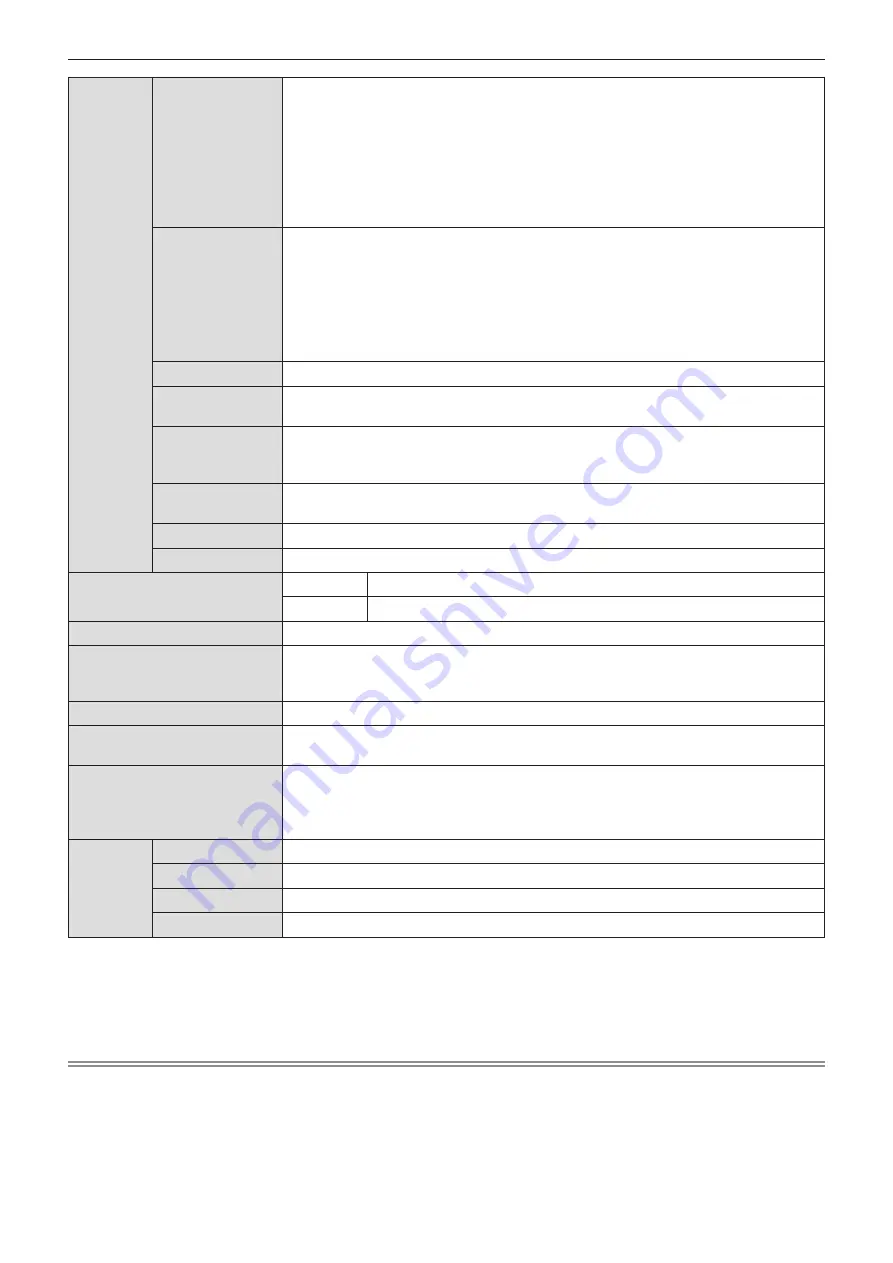
Panasonic PT-VZ470U Operating Instructions Manual Download Page 115

Terminals

<COMPUTER 1 IN>

1 set, high-density D-Sub 15 p (female)

[RGB signal] 

0.7 V [p-p] 75 Ω (When G-SYNC: 1.0 V [p-p] 75 Ω)


 HD/SYNC TTL high impedance, automatic positive/negative polarity 


compatible 

VD TTL high impedance, automatic positive/negative polarity 


compatible


(SYNC/HD and VD do not support 3 value SYNC.)

[YP

B

P

R

 signal]  Y: 1.0 V [p-p] including synchronization signal, P

B

P

R

: 0.7 V [p-p] 75 Ω

[Y/C signal] 

Y: 1.0 V [p-p], C: 0.286 V [p-p] 75 Ω

<COMPUTER 2 IN/ 

1 OUT>

1 set, high-density D-Sub 15 p (female)

[RGB signal] 

0.7 V [p-p] 75 Ω (When G-SYNC: 1.0 V [p-p] 75 Ω)


 HD/SYNC TTL high impedance, automatic positive/negative polarity 

compatible  

VD TTL high impedance, automatic positive/negative polarity 


compatible


(SYNC/HD and VD do not support 3 value SYNC.)

[YP

B

P

R

 signal]  Y: 1.0 V [p-p] including synchronization signal, P

B

P

R

: 0.7 V [p-p] 75 Ω

<VIDEO IN>

1 set, pin jack 1.0 V [p-p] 75 Ω

<HDMI 1 IN> / 

<HDMI 2 IN>

2 set (HDMI 19 pin, HDCP and Deep color compatible)

Audio signals: Linear PCM (Sampling frequency: 48 kHz/44.1 kHz/32 kHz)

<AUDIO IN>

2 set (M3 stereo mini jack, 0.5 V [rms], input impedance 22 kΩ and more)

(<AUDIO IN 2 (MIC IN)> terminal support MIC input)

1 set (Pin jack x 2 (L-R), 0.5 V [rms], input impedance 22 kΩ and more)

<VARIABLE AU-

DIO OUT>

1 set (M3 stereo mini jack, stereo monitor output compatible,

0 V [rms] to 2.0 V [rms] variable, output impedance 2.2 kΩ and less)

<SERIAL IN>

1 set (D-sub 9 pin, RS-232C compliant, for computer control use)

<LAN>

1 set (for RJ-45 network connection, PJLink compatible, 10Base-T/100Base-TX)

Power cable length

PT-VZ470

2.0 m (78-3/4”) 

PT-VZ470D

3.0 m (118-1/8”) 

Cabinet

Molded plastic

Dimensions

Width: 389 mm (15-5/16")

Height: 125 mm (4-29/32") (when adjustable feet shortened)

Depth: 332 mm (13-1/16") 

Weight

Approx. 4.8 k

g

 (10.58 lbs.) *

3

Noise level *

1

When set to [NORMAL] in [LAMP POWER] : 37 dB

When set to [ECO] in [LAMP POWER] : 29 dB

Operating environment

Operating environment temperature *

4

:

0 °C (32 °F) to 40 °C (104 °F) (Elevation: below 1 200 m (3 937'))

0 °C (32 °F) to 30 °C (86 °F) (Elevation: 1 200 m (3 937') ~ 2 700 m (8 858'))

Operating environment humidity: 20 % to 80 % (no condensation)

Remote 

control

Power supply

DC 3 V (AAA/R03/LR03 battery x 2)

Operating range

Approx. 7 m (22'11-5/8") (when operated directly in front of receiver)

Weight

63 

g

 (2.22 ozs.) (including batteries)

Dimensions

Width : 44 mm (1-23/32"), Length : 105 mm (4-1/8"), Height : 20.5 mm (13/16")

*1 

Measurement, measuring conditions and method of notation all comply with ISO/IEC 21118:2012 international standards.

*2 

Pixel-Repetition signal (dot clock frequency 27.0 MHz) only

*3  This is an average value. It may differ depending on individual product.

*4 

[LAMP POWER] will be switched to [ECO] automatically when the operating environment temperature is 35 °C (95 °F) to 

40 °C (104 °F).

Note


f

The part numbers of accessories and separately sold components are subject to change without notice.

ENGLISH


-


115

Chapter 6

Appendix — Specifications

Summary of Contents for PT-VZ470U

Page 1: ...2018 and beyond This manual is common to all the models regardless of suffixes of the Model No f for India PT VZ470D f for other countries or regions PT VZ470 Before operating this product please read...

Page 2: ...cting 41 Selecting the input signal 41 How to adjust the state of the image 41 Basic operations by using the remote control 42 Using the AUTO SETUP function 42 Using the SCREEN ADJ button 42 Controlli...

Page 3: ...WIRED LAN 81 NAME CHANGE 81 NETWORK CONTROL 82 AMX D D 82 Crestron Connected TM 82 STATUS 82 INITIALIZE 82 Network connections 83 Accessing from the web browser 84 Chapter 5 Maintenance Lamp and tempe...

Page 4: ...CISPR32 In a residential environment this equipment may cause radio interference WARNING TO REDUCE THE RISK OF FIRE OR ELECTRIC SHOCK DO NOT EXPOSE THIS PRODUCT TO RAIN OR MOISTURE o AVERTISSEMENT RI...

Page 5: ...erence when the equipment is operated in a commercial environment This equipment generates uses and can radiate radio frequency energy and if not installed and used in accordance with the instructions...

Page 6: ...al shock if the cut off plug is inserted into any 13 amp socket If a new plug is to be fitted please observe the wiring code as shown below If in any doubt please consult a qualified electrician WARNI...

Page 7: ...rtretungsberechtigter in der EU Panasonic Testing Centre Winsbergring 15 22525 Hamburg Deutschland Italiano Fabbricato da Panasonic Connect Co Ltd 4 1 62 Minoshima Hakata ku Fukuoka 812 8531 Giappone...

Page 8: ...ring 15 22525 Hamburg N metorsz g Nederlands Geproduceerd door Panasonic Connect Co Ltd 4 1 62 Minoshima Hakata ku Fukuoka 812 8531 Japan Importeur Panasonic Connect Europe GmbH Bevoegde vertegenwoord...

Page 9: ...Connect Co Ltd 4 1 62 Minoshima Hakata ku Fukuoka 812 8531 Japani Maahantuoja Panasonic Connect Europe GmbH Valtuutettu edustaja EU ssa Panasonic Testing Centre Winsbergring 15 22525 Hampuri Saksa Sve...

Page 10: ...ou o vazamento provocar calor ruptura da blindagem e produzir fogo devido ao curto circuito dos terminais N o incinere nem aque a as baterias elas n o podem ficar expostas a temperaturas superiores a...

Page 11: ...t Pull the power plug out from the wall outlet and wipe it with a dry cloth regularly Do not handle the power plug and power connector with wet hands Failure to observe this will result in electric sh...

Page 12: ...s to come into contact with metallic objects such as neck laces or hairpins z z Do not store or carry batteries together with metallic objects z z Store the batteries in a plastic bag and keep them aw...

Page 13: ...stand in front of the lens while the projector is being used Doing so can cause damage and burns to clothing z z Extremely strong light is emitted from the projector s lens Always disconnect all cable...

Page 14: ...his product incorporates the following software 1 the software developed independently by or for Panasonic Connect Co Ltd 2 the software owned by third party and licensed to Panasonic Connect Co Ltd 3...

Page 15: ...nce New lamp driving system and long life filter have greatly improved the recommended time to replace the lamp and filter so you can reduce the maintenance cost Reference f f Lamp 5 000 Hours LAMP PO...

Page 16: ...Chapter 1 Preparation This chapter describes things you need to know or check before using the projector 16 ENGLISH...

Page 17: ...F when using it at elevations lower than 1 200 m 3 937 above sea level 1 and between 0 C 32 F and 30 C 86 F when using it at high altitudes between 1 200 m 3 937 and 2 700 m 8 858 above sea level 1 Wh...

Page 18: ...n a confined space When placing the projector in a confined space a ventilation and or air conditioning system is required Exhaust heat may accumulate when the ventilation is not enough triggering the...

Page 19: ...motor r r Lamp The light source of the projector is a high pressure mercury lamp A high pressure mercury lamp has the following characteristics f f The luminance of the lamp will decrease by duration...

Page 20: ...73 TXFSX02UTRZ RGB signal cable 1 K1HY15YY0012 Attention f f After unpacking the projector discard the power cord cap and packaging material properly f f Do not use the supplied power cord for devices...

Page 21: ...or or flat panel display connected to the LAN Logo Transfer Software Windows This software allows you to transfer original images such as company logos to be displayed when projection starts to the pr...

Page 22: ...ectors x page 45 11 Number buttons Act as number buttons Use these buttons when setting the remote control codes or entering the password 12 Remote control signal transmitter 13 AUTO SETUP button Auto...

Page 23: ...by the properties of the screen f f When the remote control signal receiver is lit with a fluorescent light or other strong light source the projector may become inoperative Set the projector as far f...

Page 24: ...MP Displays the status of the internal temperature 5 Ambient Luminance sensor Detects room s light and select proper image quality 6 MENU button Displays or hides the main menu x page 48 7 ENTER butto...

Page 25: ...C compatible terminal to externally control the projector by connecting a computer 7 VIDEO IN terminal This is the terminal to input video signals 8 AUDIO IN 3 L R terminal This is the terminal to inp...

Page 26: ...t you need to complete the Initial setting and then after setting the ID number of the projector set the ID number on the remote control About Initial setting please refer to When the initial setting...

Page 27: ...or the lens cap please according to the following procedures attach the lens cap with the string of accessories 1 Thread the thinner end of the string through the hole on the lens cap Lens cap String...

Page 28: ...Chapter 2 Getting Started This chapter describes things you need to do before using the projector such as the setup and connections 28 ENGLISH...

Page 29: ...ILING PROJECTION METHOD FRONT DESK Parts for ceiling mount optional This requires an optional ceiling mount bracket Be sure to use the Projector Mount Bracket together with the ceiling mount bracket f...

Page 30: ...distance LW Maximum distance LT Height position H 0 76 30 0 78 1 27 0 025 0 228 0 70 1 15 0 002 0 186 0 68 1 12 0 022 0 201 1 02 40 1 05 1 71 0 034 0 306 0 95 1 55 0 003 0 250 0 93 1 51 0 030 0 270 1...

Page 31: ...lock the adjustable feet and rotate the adjustable feet to a proper height and tilt Extend the adjustable feet by rotating in the direction shown in the figure and retract by rotating in the opposite...

Page 32: ...SCREEN ADJUSTMENT from the POSITION menu page 57 f f Please note the followings when using the projector g g Do not touch the lens while it is moving as this could cause injury to the fingers g g Neve...

Page 33: ...lable for connection of the device prepare a necessary system connection cable to suit the device f f Video signals containing too much jitter may cause the images on the screen to randomly wobble or...

Page 34: ...standard burst signals are connected the image may be distorted In such case connect the time base corrector TBC between the projector and the external devices Note f f For an HDMI cable use an HDMI H...

Page 35: ...les Note f f If you operate the projector using the computer with the resume feature last memory you may have to reset the resume feature to operate the projector f f If the AUDIO IN SELECT settings a...

Page 36: ...Chapter 3 Basic Operations This chapter describes basic operations to start with 36 ENGLISH...

Page 37: ...ys the status of the power Check the ON G STANDBY R status of the power indicator before operating the projector Power indicator ON G STANDBY R Indicator status Status Off The power cord is unplugged...

Page 38: ...starting projection Note f f If the PROJECTOR SETUP menu ECO MANAGEMENT STANDBY MODE is set to ECO x page 74 it may take approx 10 seconds longer before the projector starts projecting after the power...

Page 39: ...e the setting from the PROJECTOR SETUP menu ECO MANAGEMENT STANDBY MODE 74 2 Press qw to switch the setting 3 Press the ENTER button f f Confirm the setting value and complete the initial setting Note...

Page 40: ...inks in red f f The projector enters standby mode when the power indicator ON G STANDBY R lights or blinks in red Note f f While the power indicator ON G STANDBY R is lighting in orange the lamp is be...

Page 41: ...the screen is correctly installed adjust the focus and zoom 1 Adjust the projection angle f f Install the projector on a flat surface and parallel to the screen so that the projected screen is rectan...

Page 42: ...seconds during automatic adjustment but it is not a malfunction f f If you press any button on the remote control during the automatic adjustment the automatic adjustment will be canceled f f If the a...

Page 43: ...nd hold the FUNCTION button for 3 seconds or more Note f f After settings have been completed the assigned menu item main menu sub menu or details menu will be displayed in ASSIGNED FUNCTION of the op...

Page 44: ...rol directly the individual adjustment screen is not displayed and the operation menu of the moving screen is displayed At this time you can adjust the magnification by using the D ZOOM button or D ZO...

Page 45: ...P TIMER button for at least 3 seconds to release the P TIMER function f f For details please refer to the DISPLAY OPTION menu P TIMER x page 69 Using the MUTE function This button allows you to turn...

Page 46: ...y If the ID SET button is pressed and no number 1 6 buttons are pressed within five seconds the ID number returns to its original value before the ID SET button was pressed f f The ID number set on th...

Page 47: ...Chapter 4 Settings This chapter describes the settings and adjustments you can make using the on screen menu ENGLISH 47...

Page 48: ...item from the main menu f f The selected item is highlighted in yellow 3 Press the ENTER button f f The submenu is displayed and submenu items become selectable 4 Press as to select the desired sub me...

Page 49: ...e values adjusted in the menu items are restored to the factory default settings button 1 Press the DEFAULT button on the remote control Note f f You cannot reset all the settings to the factory defau...

Page 50: ...u item Factory default Page REALTIME KEYSTONE ON 57 SCREEN ADJUSTMENT 57 SHIFT 61 DOT CLOCK 1 0 61 CLOCK PHASE 1 0 61 OVER SCAN 62 ASPECT 62 FRAME LOCK 1 OFF 63 1 Only for still image signals LANGUAGE...

Page 51: ...OCK PASSWORD 79 CONTROL DEVICE SETUP 80 NETWORK Sub menu item Factory default Page WIRED LAN 81 NAME CHANGE 81 NETWORK CONTROL ON 82 AMX D D OFF 82 Crestron Connected TM OFF 82 STATUS 82 INITIALIZE 82...

Page 52: ...picture becomes suitable for projecting on a white board CINEMA 1 The picture becomes suitable for movie sources NATURAL 2 The picture becomes suitable for use in low light areas 1 Only for the movie...

Page 53: ...en is displayed 3 Press qw to adjust the level Operation Adjustment Adjustment range Press the w button Adjusts skin tone toward greenish color 32 32 Press the q button Adjusts skin tone toward reddis...

Page 54: ...ss the q button Deemphasizes red in highlight areas CONTRAST G Press the w button Emphasizes green in highlight areas 32 32 Press the q button Deemphasizes green in highlight areas CONTRAST B Press th...

Page 55: ...s qw to switch the item f f The items will switch each time you press the button OFF Disables NOISE REDUCTION ON Enables NOISE REDUCTION 1 When COMPUTER1 INPUT SETTING is set to Y C page 71 Attention...

Page 56: ...terminal is selected f f For 525i 480i 625i 576i 525p 480p and 625p 576p input Select AUTO RGB or YCB CR f f For other movie based signal input Select AUTO RGB or YPB PR 1 When the COMPUTER 2 IN 1 OU...

Page 57: ...ect image imperfectly manual keystone is required f f The REALTIME KEYSTONE function cannot work when the FRONT CEILING or REAR CEILING feature is selected in PROJECTION METHOD in the PROJECTOR SETUP...

Page 58: ...screen is displayed 5 Press as to select LENS THROW RATIO 6 Press the ENTER button f f The LENS THROW RATIO individual adjustment screen is displayed 7 Press qw to adjust the item f f The adjustment v...

Page 59: ...T 2 Press the ENTER button f f The SCREEN ADJUSTMENT screen is displayed 3 Press as to select CORNER CORRECTION 4 Press the ENTER button f f The CORNER CORRECTION screen is displayed 5 Press as to sel...

Page 60: ...Setting KEYSTONE Adjusting KEYSTONE x page 58 Adjusting ARC 1 Press asqw to adjust Items Operation Adjustment H Press the q button The top and the bottom of horizontal line will be bulge Press the w b...

Page 61: ...ge position moves up Press the s button The image position moves down Horizontal right and left adjustment Press the w button The image position moves to the right Press the q button The image positio...

Page 62: ...H FIT Displays images using the entire width of the screen When signals have the aspect ratio vertically longer than the aspect ratio of the screen selected in SCREEN FORMAT the images are displayed...

Page 63: ...creator of the images FRAME LOCK Only for still image signals input This setting is available for specific computer signals Set when the movie is distorted 1 Press as to select FRAME LOCK 2 Press qw...

Page 64: ...s menus settings adjustment screens control button names etc are displayed in the selected language f f The language can be changed to English German French Italian Spanish Portuguese Dutch Swedish Fi...

Page 65: ...ach time you press the button DETAILED Displays the name of input terminal and input signal graphically OFF Disables the input guide SIMPLE Displays the name of input terminal and input signal OSD POS...

Page 66: ...al 0 1023 Select when the DVI terminal output of an external device such as a computer is connected to the HDMI 1 IN HDMI 2 IN terminal via a conversion cable or similar cable Select also when the HDM...

Page 67: ...ptimum image position for the set screen Set as necessary for the screen in use 1 Press as to select SCREEN SETTING 2 Press the ENTER button f f The SCREEN SETTING screen is displayed 3 Press as to se...

Page 68: ...function only when the AUTO SETUP button is pressed SIGNAL SEARCH When the power is turned on this function automatically detects the terminal which signals are input and sets the function to switch 1...

Page 69: ...and operate the presentation timer function Setting the mode 1 Press as to select P TIMER 2 Press the ENTER button f f The P TIMER screen is displayed 3 Press as to select MODE 4 Press qw to switch t...

Page 70: ...he start time becomes the value set at TIMER f f The time gauge turns clockwise when COUNT UP is set and turns counterclockwise when COUNT DOWN is set Ending the presentation timer 1 Press as to selec...

Page 71: ...ial number of the projector 1 The following conversion is required to calculate the rough estimate for lamp replacement Formula for lamp replacement time rough estimate A 1 B 5 7 f f A Runtime which i...

Page 72: ...ol x page 45 for how to set the ID number on the remote control INITIAL START UP Set the method of start up when the power cord plugged into the AC outlet 1 Press as to select INITIAL START UP 2 Press...

Page 73: ...d automatically in the following cases When the lamp lighting is just completed or the setting of LAMP POWER is just completed etc f f When AUTO POWER SAVE is set to OFF settings of AMBIENT LIGHT DETE...

Page 74: ...Z570 series VW355N series VX425N series VW350 series VX420 series VZ575N series VW535N series VX605N series VZ570 series VW530 series VX600 series VX60 VX50 EZ580 series EW640 series EX610 series EW54...

Page 75: ...TING 2 Press the ENTER button f f The AUDIO SETTING screen is displayed 3 Press as to select MUTE 4 Press qw to switch the item OFF Audio is output ON Audio is not output Setting the audio output duri...

Page 76: ...button OFF Disables the MIC ON AUDIO IN 2 terminal switches to MIC input 5 Press as to select MIC GAIN 6 Press qw to adjust the level Operation Adjustment Range Press the w button Turns up the MIC mi...

Page 77: ...ILTER COUNTER RESET screen is displayed 3 Press qw to select OK and then press the ENTER button INITIALIZE ALL Return various setting values to their factory default settings 1 Press as to select INIT...

Page 78: ...turned on INITIALIZE ALL is executed or INITIALIZE in the NETWORK menu is executed When the entered password is incorrect the operation will be restricted to the power button v b on the control panel...

Page 79: ...ged MENU LOCK Display the menu by the MENU button and set whether or not to enable menu operations 1 Press as to select MENU LOCK 2 Press qw to switch the item f f The items will switch each time you...

Page 80: ...le the button operations DISABLE Disable the button operations f f A confirmation screen will be displayed when you change ENABLE to DISABLE then proceed to Step 5 5 Press qw to select OK and then pre...

Page 81: ...if DHCP server is not used DNS2 Enter the alternate DNS server address if DHCP server is not used 4 Press as to select OK and press the ENTER button r r Default wired LAN settings f f The following s...

Page 82: ...restron Connected TM Set to ON to control with Crestron Connected of Crestron Electronics Inc 1 Press as to select Crestron Connected TM 2 Press qw to switch the item f f The items will switch each ti...

Page 83: ...estron com resources get roomview Computer that can be used In order to use the Web control function a Web browser is required Confirm that the Web browser can be used beforehand OS Compatible web bro...

Page 84: ...ings are the default settings the computer can be used with the following network settings IP ADDRESS 192 168 10 101 SUBNET MASK 255 255 255 0 DEFAULT GATEWAY 192 168 10 1 Accessing from the web brows...

Page 85: ...ng the screen for the web control the screen may become white for a moment but it is not a malfunction Description of each item 1 2 3 4 5 6 PT VZ470 1 Page tab Switches pages by clicking this item 2 S...

Page 86: ...r Description FAN Trouble has occurred in the fan or its drive circuit Consult your dealer FAN INTAKE1 Trouble has occurred in the intake fan 1 FAN INTAKE2 Trouble has occurred in the intake fan 2 FAN...

Page 87: ...E Adjusts the volume level 3 PICTURE MODE Switches the picture mode 4 AV MUTE Switches between AV mute on off 5 POWER Turns on off the power 6 CLOSED CAPTION Switches the closed caption mode Advanced...

Page 88: ...ter the DNS1 server address Permissible characters for the entry of DNS1 server address primary Numbers 0 9 period Example 192 168 0 253 6 DNS2 Enter the DNS2 server address Permissible characters for...

Page 89: ...AME Enter the IP address or the server name of the E mail server SMTP To enter the server name the DNS server needs to be set up 3 MAIL FROM Enter the E mail address of the projector Up to 63 characte...

Page 90: ...e settings Authentication set up page Set the authentication items when POP authentication or SMTP authentication is necessary to send an E mail Click Detailed set up Authentication set up 1 2 3 4 5 6...

Page 91: ...RATURE OFF check system FAN OK INTAKE AIR TEMPERATURE OK EXHAUST AIR TEMPERATURE OK LAMP REMAIN TIME OK LAMP STATUS OK APERTURE CONTRAST SHUTTER OK AIR FILTER OK Error code 00 00 00 00 00 00 00 00 Int...

Page 92: ...31 degC 87 degF Exhaust air temperature 37 degC 98 degF PROJECTOR RUNTIME 800 H LAMP ECO 500 H LAMP NORMAL 100 H LAMP REMAIN 3400 H Current status MAIN VERSION 1 00 NETWORK VERSION 1 00 SUB VERSION 1...

Page 93: ...unction 5 AV MUTE DETECTION Enable ON disable OFF the AV mute detection function 6 POWER MANAGEMENT Select the power consumption mode 7 TIMER Select the time that the lamp is turned off when the POWER...

Page 94: ...word Up to 16 characters in single byte Password Retype Enter the desired new password again 4 OK Determines the change of password User account 1 2 3 1 Account Displays the account to change 2 New Us...

Page 95: ...not displayed on the web control screen The control page of Crestron Connected is displayed by clicking Crestron Connected TM It is not displayed if Adobe Flash Player is not installed on the compute...

Page 96: ...lays the current setting SubnetMask Displays the current setting DefaultGateway Displays the current setting DNSServer Displays the current setting 5 Exit Returns to the control page Info page Click I...

Page 97: ...p page Click Help on the control page The Help Desk window is displayed 1 1 Help Desk Send receive messages to from an administrator who uses Crestron Connected ENGLISH 97 Chapter 4 Settings NETWORK m...

Page 98: ...Chapter 5 Maintenance This chapter describes methods of inspection when there are problems maintenance and replacement of the units 98 ENGLISH...

Page 99: ...aking the preceding measures ask your dealer for repair Temperature indicator TEMP Indicator status Lighting in red Blinking in red Blinking in red Slow Status The air filter unit is clogged internal...

Page 100: ...in dusty environment Replace the air filter unit in the following cases f f If the air filter unit is clogged a Temperature Warning message is displayed on the screen and then the temperature indicato...

Page 101: ...The lamp unit is a consumable component Refer to When to replace the lamp unit x page 102 for details about the replacement cycle When purchasing the optional Replacement Lamp Unit Model No ET LAV400...

Page 102: ...above equation 5 000 hours has elapsed the lamp turns off automatically after approximately 10 minutes as it will cause malfunction of the projector Time which is ob tained by the above equation On s...

Page 103: ...screwdriver f f When you experience difficulty in installing the lamp unit remove it and try again If you use force to install the lamp unit the connector may be damaged 6 Attach the lamp cover Tight...

Page 104: ...ve been turned on f f Is the audio input selection in AUDIO SETTING set correctly 34 35 43 75 45 70 34 35 45 75 75 The remote control does not operate f f The batteries may be weak f f The batteries m...

Page 105: ...Chapter 6 Appendix This chapter describes specifications and after sales service for the projector ENGLISH 105...

Page 106: ...Indicates lamp errors range 0 2 3rd byte Indicates temperature errors range 0 2 4th byte Fixed at 0 5th byte Indicates filter errors range 0 2 6th byte Indicates other errors range 0 2 LAMP Lamp stat...

Page 107: ...rithm f f xxxxxx yyyyy zzzzzzzz xxxxxx Administrator rights user name for WEB CONTROL Default user name is admin1 yyyyy Password of above administrator rights user Default password is panasonic zzzzzz...

Page 108: ...0d Data length 9 bytes 1 byte 1 byte 1 byte f fMode 0 Non protect mode Command transmission method Transmit by the following command format r r Transmitted data Header Data section Termination symbol...

Page 109: ...tents NC TXD Transmitted data RXD Received data NC GND Earth NC CTS Connected internally RTS NC Communication conditions Factory default Signal level RS 232C compliant Sync method Asynchronous Baud ra...

Page 110: ...nsmitting multiple commands be sure to wait until 0 5 seconds has elapsed after receiving the response from the projector before sending the next command When transmitting a command which does not nee...

Page 111: ...ower on To check if the power is on use the Power query command POF Power off IIS INPUT selection VID RG1 RG2 HD1 HD2 VIDEO RGB1 RGB2 HDMI1 HDMI2 OFZ Freeze 0 OFF 1 ON AUU Volume up AUD Volume down DZ...

Page 112: ...H l 1125 1080 24sF 1 920 x 1 080i 27 0 48 0 74 3 R Y H 1125 1080 25p 1 920 x 1 080 28 1 25 0 74 3 R Y H 1125 1080 30p 1 920 x 1 080 33 8 30 0 74 3 R Y H 1125 1080 60p 1 920 x 1 080 67 5 60 0 148 5 R...

Page 113: ...H 1 920 x 1 080 5 67 2 60 0 173 0 R WUXGA 1 920 x 1 200 61 8 49 9 158 3 R H 1 920 x 1 200 4 74 0 60 0 154 0 R H l l 1 920 x 1 200 5 74 6 59 9 193 3 R 1 Where marked l signals indicates in Plug and Pla...

Page 114: ...orizontal 15 63 kHz Vertical 50 Hz For RGB signal Horizontal 15 kHz to 91 kHz Vertical 24 Hz to 100 Hz Dot clock frequency 162 MHz or less For YPB PR signal 525i 480i Horizontal 15 73 kHz Vertical 59...

Page 115: ...d less SERIAL IN 1 set D sub 9 pin RS 232C compliant for computer control use LAN 1 set for RJ 45 network connection PJLink compatible 10Base T 100Base TX Power cable length PT VZ470 2 0 m 78 3 4 PT V...

Page 116: ...Dimensions Unit mm inch 104 6 4 1 8 63 8 2 1 2 332 0 13 1 16 389 0 15 5 16 250 0 9 27 32 125 0 4 29 32 337 0 13 9 32 Actual dimension may differ by product 116 ENGLISH Chapter 6 Appendix Dimensions...

Page 117: ...ot manufactured by Panasonic Connect Co Ltd or the inappropriate choice of location for installation even if the warranty period of the projector has not expired f f Unused products must be removed pr...

Page 118: ...ZE ALL 77 INITIAL START UP 72 INPUT SELECT button Projector body 24 Installation mode 29 IRIS 54 L Lamp indicator 24 99 LAMP POWER 72 LANGUAGE 64 List of compatible signals 112 M Main menu 49 Maintena...

Page 119: ...batteries must not be mixed with general household waste For proper treatment recovery and recycling of old products and used batteries please take them to applicable collection points in accordance w...

Reviews: