


[LENS THROW RATIO]
Set the throw ratio. The adjustable range is 0.9 ~ 2.3.
Select a value close to the value obtained by dividing the actual projection distance by the projection
screen width.
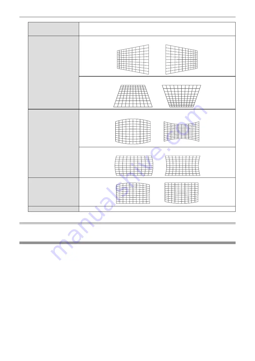
[KEYSTONE]
[H]
[V]
[ARC]
[H]
[V]
[BALANCE]
[MAINTAIN ASPECT RATIO]
To adjust without changing the aspect ratio, set it to [ON].
Note
f
Pressing the <ENTER> button while the individual adjustment screen is displayed can switch to the individual adjustment screen of other
items.
[SHIFT]
(Only for COMPUTER1 / COMPUTER2 signal input)
Move the image position vertically or horizontally if the image position projected on the screen is shifted even
when the relative position of the projector and the screen is installed correctly.
1) Press
as
to select [SHIFT].
2) Press the <ENTER> button.
f
The
[SHIFT]
screen is displayed.
3) Press
asqw
to adjust the position.
60 -
ENGLISH
Chapter 4 Settings - [POSITION] menu


