


6 - ENGLISH
Read this first!
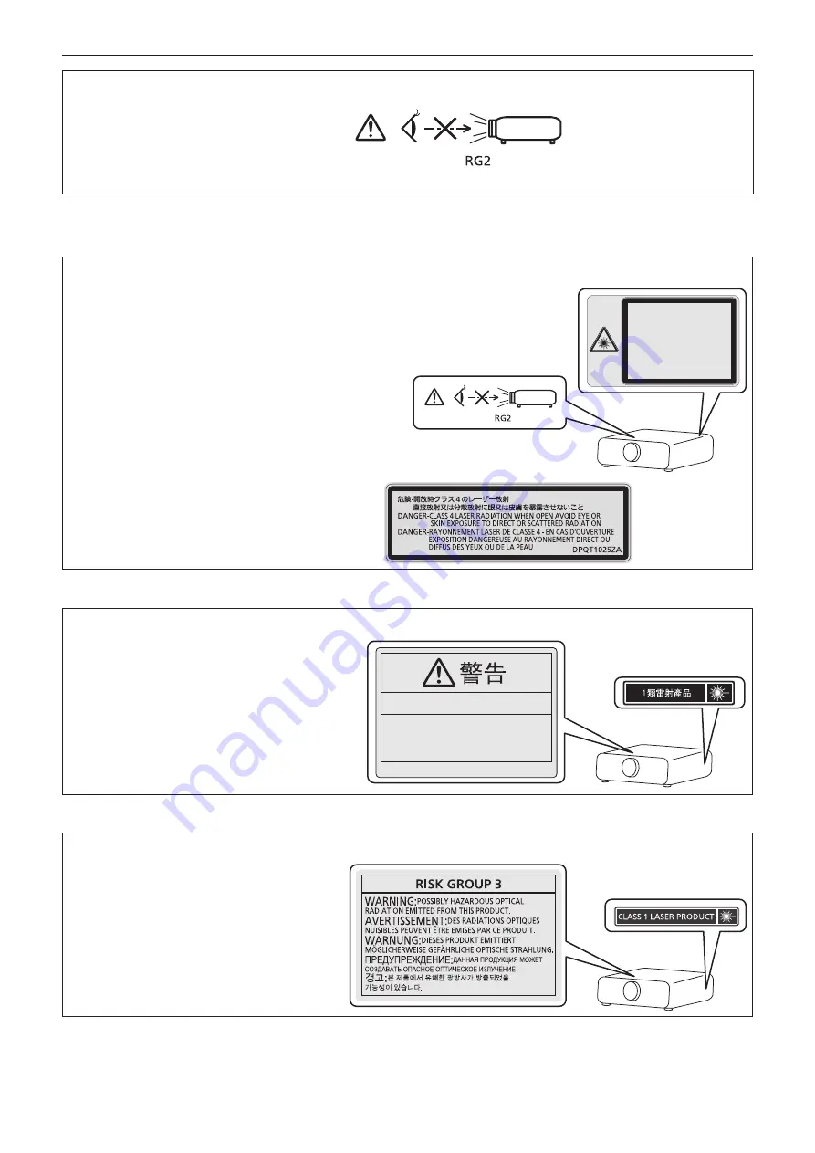
WARNING:
Do not look at the light emitted from the lens while the projector is being used.
As with any bright source, do not stare into the direct beam, RG2 IEC 62471-5:2015.
Indicated on the projector
Notice on laser
(for USA and Canada)
This projector is the Class 3R laser product that complies with IEC 60825-1:2007.
DPQT1024YA
For North America
“Complies with 21 CFR Parts 1040.10 and 1040.11
except for deviations pursuant to Laser Notice
No.50 dated June 24.2007”
IEC 60825-1:2007
LASER RADIATION
AVOID DIRECT EYE EXPOSURE
CLASS 3R LASER PRODUCT
WAVE LENGTH:448-462nm
MAXIMUM OUTPUT:248mW
PULSE DURATION:1.1ms
IEC 60825-1:2007
RAYONNEMENT LASER
EXPOSITION DIRECTE DANGEREUSE POUR LES YEUX
APPAREIL
À
LASER DE CLASSE 3R
LONGUEURS D'ONDES:448-462nm
MAXIMALE DU RAYONNEMENT:248mW
DUR
É
E DE L'IMPULSION:1.1ms
130C
(Inside of product)
(for Taiwan)
This projector is the Class 1 laser product that complies with IEC/EN 60825-1:2014.
DPQT1242ZA
此產品可能含有危險的光學輻射。
危險等級 3
(for India)
This projector is the Class 1 laser product that complies with IEC/EN 60825-1:2014.
TQFX340


