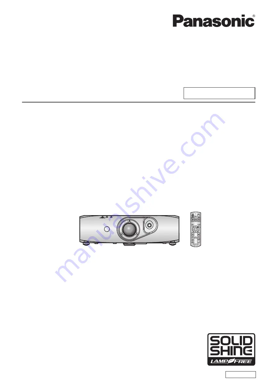
Panasonic PT-RW330U Operating Instructions Manual Download Page 1

Thank you for purchasing this Panasonic product.


Before operating this product, please read the instructions carefully and save this manual 

for future use.


Before using your projector, be sure to read “Read this first!” (

x

 pages 2 to 8).

Model No. 

PT-RZ370U


PT-RW330U

TQBJ0490

DLP

TM

 Projector  

Commercial Use

Operating Instructions

Functional Manual

ENGLISH

Summary of Contents for PT-RW330U

Page 1: ...oduct please read the instructions carefully and save this manual for future use Before using your projector be sure to read Read this first x pages 2 to 8 Model No PT RZ370U PT RW330U TQBJ0490 DLPTM Projector Commercial Use Operating Instructions Functional Manual ENGLISH ...

Page 2: ...lateral triangle is intended to alert the user to the presence of uninsulated dangerous voltage within the product s enclosure that may be of sufficient magnitude to constitute a risk of electric shock to persons The exclamation point within an equilateral triangle is intended to alert the user to the presence of important operating and maintenance servicing instructions in the literature accompan...

Page 3: ...determined by turning the equipment off and on the user is encouraged to try to correct the interference by one or more of the following measures z z Reorient or relocate the receiving antenna z z Increase the separation between the equipment and receiver z z Connect the equipment into an outlet on a circuit different from that to which the receiver is connected z z Consult the dealer or an experi...

Page 4: ...erted correctly electric shocks or overheating will result z z Do not use plugs which are damaged or wall outlets which are coming loose from the wall Clean the power plug regularly to prevent it from becoming covered in dust Failure to observe this will cause a fire z z If dust builds up on the power plug the resulting humidity can damage the insulation Pull the power plug out from the wall outle...

Page 5: ...o may cause exposure to dangerous laser radiation z z The laser module is built in this projector Follow procedures specified in the Operating Instructions to make operations and adjustments Do not allow metal objects flammable objects or liquids to enter inside of the projector Do not allow the projector to get wet Doing so may cause short circuits or overheating and result in fire electric shock...

Page 6: ...Do not use a new battery together with an old battery or mix different types of batteries z z Do not use batteries with the outer cover peeling away or removed If the battery fluid leaks do not touch it with bare hands and take the following measures if necessary z z Battery fluid on your skin or clothing could result in skin inflammation or injury Rinse with clean water and seek medical advice im...

Page 7: ...sing or internal components to deteriorate or result in fire z z Take particular care in locations exposed to direct sunlight or near stoves Do not place your hands or other objects close to the air exhaust port Doing so will cause burns or damage your hands or other objects z z Heated air comes out of the air exhaust port Do not place your hands or face or objects which cannot withstand heat clos...

Page 8: ...a bateria pode irritar a garganta danificar o lacre do invólucro ou o vazamento provocar calor ruptura da blindagem e produzir fogo devido ao curto circuito dos terminais Não incinere nem aqueça as baterias elas não podem ficar expostas a temperaturas superiores a 100 C 212 F O gás liberado pela bateria pode irritar a garganta danificar o lacre do invólucro ou o vazamento provocar calor ruptura da...

Page 9: ...A is a trademark or registered trademark of Video Electronics Standards Association f f RoomView and Crestron RoomView are registered trademarks of Crestron Electronics Inc Crestron Connected and Fusion RV are trademarks of Crestron Electronics Inc f f Adobe Flash Player is a trademark or registered trademark of Adobe Systems Inc in the United Stated and or in other countries f f All other names c...

Page 10: ...e projector Energy conservation achieved through the ECO function The function to reduce power consumption is installed which is optimizing the light source power according to the brightness of the surroundings input signal and video mute status Quick Steps For details refer to the corresponding pages 1 Set up the projector x page 24 c 2 Connect with external devices x page 27 c 3 Connect the powe...

Page 11: ...itching on off the projector 32 Connecting the power cord 32 Power indicator 32 Switching on the projector 33 Making adjustments and selections 34 Switching off the projector 34 Projecting 35 Selecting the input signal 35 Adjusting the image 35 Adjustment range by the lens position shift optical shift 36 Operating with the remote control 37 Using the AV mute function 37 Using the Freeze function 3...

Page 12: ...list 83 Renaming the registered signal 83 Deleting the registered data 84 SECURITY menu 85 SECURITY PASSWORD 85 SECURITY PASSWORD CHANGE 85 TEXT DISPLAY 86 TEXT CHANGE 86 MENU LOCK 86 MENU LOCK PASSWORD 86 CONTROL DEVICE SETUP 87 NETWORK menu 88 DIGITAL LINK MODE 88 DIGITAL LINK SETUP 88 DIGITAL LINK STATUS 89 NETWORK SETUP 90 NETWORK CONTROL 90 NETWORK STATUS 91 Network connections 91 Connecting ...

Page 13: ...ENGLISH 13 Chapter 1 Preparation This chapter describes things you need to know or check before using the projector ...

Page 14: ...e DLP chips r rBe sure to ask a specialized technician or your dealer when installing the product to a ceiling The optional ceiling mount bracket is required Model No ET PKR100H for high ceilings ET PKR100S for low ceilings r rAsk a qualified technician or your dealer to install the cable wiring for DIGITAL LINK connection Image and sound may be disrupted if cable transmission characteristics can ...

Page 15: ... on top of each other f f Do not block the ventilation ports intake and exhaust of the projector f f Prevent hot and cool air from the air conditioning system to blow directly to the ventilation ports intake and exhaust of the projector PP RU ORQJHU PP RU ORQJHU PP RU ORQJHU PP RU ORQJHU f f Do not install the projector in a confined space When it is necessary to install the projector in a confine...

Page 16: ...een to prevent outside light or light from indoor lamps from shining onto the screen f f The high clarity projection lens is thermally affected by the light from the light source making the focus unstable in the period just after switching on the power The focus stabilizes when an image is projected continuously for 30 minutes or more r r Do not touch the surface of the projection lens with your b...

Page 17: ...of the supplied CD ROM are as follows Instruction list PDF Operating Instructions Functional Manual Multi Projector Monitoring Control Software Operation Manual Logo Transfer Software Operating Instructions List of Compatible Projector Models This is a list of projectors that are compatible with the software contained in the CD ROM and their restrictions Software Multi Projector Monitoring Control...

Page 18: ... to show on the screen x page 58 1 Press as to select the display language 17 5 1 7 6 77 1 6 7 6 7 2 Press the ENTER button to proceed to the initial setting Initial setting projector setup Set each item 1 Press as to select an item 2 Press qw to switch the setting 17 5 1 7 6 77 1 0 18 6 7 1 6 7 352 7 21 0 7 2 22 1 21 7 21 6 5 1 250 7 6 5 1 326 7 21 5217 225 225 6 77 1 f f Refer to the following p...

Page 19: ...adjusted automatically x page 38 11 asqw buttons RETURN button ENTER button Used to navigate through the menu screen Also used to enter a SECURITY password or character input 12 AV MUTE button Use to temporarily turn off the audio and video x page 37 13 ECO button Displays the setting screen related to ECO management x page 39 14 VOLUME VOLUME button Adjusts the audio output volume x page 39 15 St...

Page 20: ... Adjustable feet Adjusts the projection angle 6 Remote control signal receiver front 7 Projection lens 8 Lens shift lever Adjusts the projection position 9 Air intake port 10 Air exhaust port 11 Remote control signal receiver rear 12 Security slot This security slot is compatible with the Kensington security cables 13 Connecting terminals x page 21 14 AC IN terminal Connect the supplied power cord...

Page 21: ...his is the LAN terminal to connect to the network This is also used when connecting an audio and video signal sending device via the LAN terminal 2 HDMI IN terminal This is the terminal to input HDMI signals 3 DVI I IN terminal This is the terminal to input DVI D and DVI A signals RGB signals or YCBCR YPBPR 4 COMPUTER IN terminal This is the terminal to input RGB or YCBCR YPBPR signals from a comp...

Page 22: ...jector if you press the ID ALL button on the remote control even if you do not know the projector ID How to set 1 Press the ID SET button on the remote control 2 Within five seconds press the one digit ID number set on the projector using the number 1 6 buttons f f If you press the ID ALL button you can control the projectors regardless of the ID number setting of the projector Attention f f Since...

Page 23: ...ENGLISH 23 Chapter 2 Getting Started This chapter describes things you need to do before using the projector such as the setup and connections ...

Page 24: ...Menu item 1 Method Menu item 1 Method PROJECTION METHOD REAR CEILING PROJECTION METHOD FRONT FLOOR COOLING CONDITION CEILING SETTING COOLING CONDITION FLOOR SETTING 1 For menu item details refer to the PROJECTOR SETUP menu PROJECTION METHOD x page 69 and COOLING CONDITION x page 70 Parts for ceiling mount optional You can install the projector on the ceiling using the optional ceiling mount bracke...

Page 25: ... ratio Diagonal SD Min projection distance LW Max projection distance LT Min projection distance LW Max projection distance LT Min projection distance LW Max projection distance LT 1 02 40 1 55 5 10 3 16 10 39 1 26 4 13 2 58 8 47 1 36 4 48 2 79 9 16 1 27 50 1 95 6 42 3 97 13 02 1 59 5 21 3 23 10 62 1 72 5 65 3 50 11 49 1 52 60 2 36 7 74 4 77 15 66 1 91 6 29 3 89 12 77 2 07 6 82 4 21 13 81 1 78 70 ...

Page 26: ...rojection distance The unit of the formula is m The values of the following calculation results contain slight error For PT RZ370U 4 3 aspect ratio 16 9 aspect ratio 16 10 aspect ratio Screen size Height SH SD x 0 6 SD x 0 490 SD x 0 530 Screen size Width SW SD x 0 8 SD x 0 872 SD x 0 848 Min projection distance LW 1 5854 x SD 0 0544 1 2955 x SD 0 0544 1 4004 x SD 0 0544 Max projection distance LT...

Page 27: ...ing too much jitter may cause the images on the screen to randomly wobble or wafture In this case a time base corrector TBC must be connected f f The projector accepts video signals analog RGB signals synchronous signals are TTL level and digital signals f f Some computer models are not compatible with the projector f f Use a cable compensator when you connect devices to the projector using long c...

Page 28: ...ge may be distorted In such case connect the time base corrector TBC between the projector f f Use a commercial HDMI DVI conversion cable with a ferrite core Note f f The DVI I IN terminal can be connected to HDMI or DVI I compliant devices However images may not appear or may not be displayed properly on some devices x page 62 f f For an HDMI cable use an HDMI High Speed cable that conforms to HD...

Page 29: ...I I IN terminal for digital input supports single link only f f For signals that the projector can project refer to List of compatible signals x page 121 f f If you operate the projector using the computer with the resume feature last memory you may have to reset the resume feature to operate the projector f f During DVI digital signal input EDID settings may be necessary depending on the external...

Page 30: ...ed pair cable transmitter in between the twisted pair cable transmitter of other company and the projector This may cause sound and image to be disrupted f f Do not pull cables forcefully Also do not bend or fold cables unnecessarily f f To reduce noise stretch out the cables between the twisted pair cable transmitter and the projector without any loops as much as possible before setting them up a...

Page 31: ...ENGLISH 31 Chapter 3 Basic Operations This chapter describes basic operations to start with ...

Page 32: ...ower cord 1 Check the shapes of the AC IN terminal on the side of the projector body and the power cord connector and insert the plug completely in the correct direction until you hear the hooks click in place Removing the power cord 1 Confirm that the MAIN POWER switch of the main side is on the OFF side and remove the power plug from the outlet 2 Remove the power cord connector from the AC IN te...

Page 33: ...ge is soon projected on the screen Note f f If the projector is switched on at around 0 C 32 F a warm up period of approximately five minutes may be necessary until an image is displayed The temperature indicator TEMP lights during the warm up period When the warm up is completed the temperature indicator TEMP turns off and the projection starts Refer to Managing the indicated problems x page 109 ...

Page 34: ... button f f The POWER OFF STANDBY confirmation screen is displayed 2 Press qw to select OK and press the ENTER button Or press the power v b button again f f Projection of the image stops 3 Wait for a few seconds until the power indicator ON G STANDBY R of the projector body lights flashes in red 4 Press the OFF side of the MAIN POWER switch to turn off the power Note f f The projector consumes po...

Page 35: ...to the screen and install on a flat surface so that the projection screen is rectangular f f If the projector is tilted further downward than the screen adjust the projection screen to be rectangular by extending the adjustable feet f f Refer to Adjusting adjustable feet x page 26 for details 2 Release the lens shift lever lock by turning it counter clockwise 3 Adjust the lens shift Fig 1 f f Adju...

Page 36: ...can be adjusted with the optical axis shift based on the standard projection position in the range shown in the following figures PT RZ370U 9 9 3URMHFWLRQ VFUHHQ ZLGWK 6WDQGDUG SURMHFWLRQ SRVLWLRQ 3URMHFWLRQ VFUHHQ KHLJKW 9 PT RW330U 9 9 3URMHFWLRQ VFUHHQ ZLGWK 6WDQGDUG SURMHFWLRQ SRVLWLRQ 3URMHFWLRQ VFUHHQ KHLJKW 9 The numerical values in the preceding diagrams represent a case in which the proje...

Page 37: ...o and video Note f f The power indicator ON G STANDBY R flashes slowly when the projector is in AV mute mode f f The projector has no built in speakers There is audio output from the external sound system connected to the VARIABLE AUDIO OUT terminal Using the Freeze function The projected image can be paused temporarily and the audio muted regardless of the playback of the external equipment butto...

Page 38: ...tic adjustment mode Avoid supplying images that include halftones or gradation such as photographs and computer graphics button 1 Press the AUTO SETUP button f f COMPLETE is displayed when it has completed without any problem Note f f The clock phase may shift even if it has completed without any incident In this case adjust with the POSITION menu CLOCK PHASE x page 53 f f If an image with blurred...

Page 39: ... menu 2 Press and hold any buttons from FUNC1 to FUNC3 for three seconds or more Note f f When settings are completed F1 F2 or F3 is displayed on the left of the menu item main menu sub menu or details menu assigned when FUNC1 FUNC2 or FUNC3 is set respectively f f To clear the assigned functions perform the PROJECTOR SETUP menu FUNCTION BUTTON x page 77 Using the ECO management function The setti...

Page 40: ...40 ENGLISH Chapter 4 Settings This chapter describes the settings and adjustments you can make using the on screen menu ...

Page 41: ...ss as to select an item from the main menu f f The selected item is highlighted in yellow 17 5 0 1 0 18 3 785 326 7 21 9 1 0 18 63 1 8 63 237 21 352 725 6 783 7 67 3 77 51 6 1 67 6 85 7 1 7 25 7 1 0 18 6 7 68 0 18 3 Press the ENTER button f f The sub menu items of the selected main menu are displayed 17 5 326 7 21 6 7 1250 63 7 220 2 3 6 6721 0 18 6 7 68 0 18 4 Press as to select a sub menu and pr...

Page 42: ...button on the remote control 2175 67 867 Note f f You cannot reset all the settings to the factory default at a time f f To reset all the settings adjusted in the sub menu item to the factory default at a time execute the PROJECTOR SETUP menu INITIALIZE x page 81 f f Some items cannot be reset by pressing the DEFAULT button Adjust each item manually f f The square mark under the bar scale in the i...

Page 43: ...OR TEMPERATURE DEFAULT 47 DAYLIGHT VIEW AUTO 49 SHARPNESS 6 1 49 NOISE REDUCTION OFF 1 49 SYSTEM SELECTOR YPBPR 1 50 1 Depends on the signal input Note f f The factory default settings may vary depending on the picture mode POSITION Sub menu item Factory default Page SHIFT 51 ASPECT NORMAL 52 ZOOM 52 CLOCK PHASE 16 1 53 KEYSTONE 0 54 1 Depends on the signal input ADVANCED MENU Sub menu item Factor...

Page 44: ...63 ON SCREEN DISPLAY 63 CLOSED CAPTION SETTING 65 BACK COLOR BLUE 66 STARTUP LOGO DEFAULT LOGO 66 SUB MEMORY LIST 67 FREEZE 67 AV MUTE 68 1 Only for PT RW330U PROJECTOR SETUP Sub menu item Factory default Page PROJECTOR ID ALL 69 PROJECTION METHOD FRONT FLOOR 69 COOLING CONDITION FLOOR SETTING 70 ECO MANAGEMENT 70 SCHEDULE OFF 72 INITIAL STARTUP LAST MEMORY 74 STARTUP INPUT SELECT LAST USED 74 DIG...

Page 45: ...TWORK Sub menu item Factory default Page DIGITAL LINK MODE AUTO 88 DIGITAL LINK SETUP 88 DIGITAL LINK STATUS 89 NETWORK SETUP 90 NETWORK CONTROL 90 NETWORK STATUS 91 DIGITAL LINK Details x page 107 Note f f Some items may not be adjusted or used for certain signal formats to be input to the projector f f The menu items that cannot be adjusted or used are shown in gray characters and they cannot be...

Page 46: ... becomes similar to that of DICOM Part 14 Grayscale Standard DYNAMIC The light output is maximized for use in bright areas 1 Use the factory default for the settings other than PICTURE MODE Note f f The factory default picture mode is GRAPHIC for still image input signals and STANDARD for movie based input signals f f DICOM is an abbreviation of Digital Imaging and Communication in Medicine and is...

Page 47: ...button Weakens colors TINT You can adjust the skin tone in the projected image 1 Press as to select TINT 2 Press qw or the ENTER button f f The TINT individual adjustment screen is displayed 3 Press qw to adjust the level Operation Adjustment Range Press the w button Adjusts skin tone toward greenish color 31 31 Press the q button Adjusts skin tone toward reddish purple COLOR TEMPERATURE You can s...

Page 48: ... Press the w button Deepens green Press the q button Weakens green BLUE Press the w button Deepens blue Press the q button Weakens blue Note f f Adjust COLOR TEMPERATURE correctly All colors will not be displayed properly unless adequate adjustment is made If the adjustment does not look suitable you can press the DEFAULT button on the remote control to return the setting for the selected item onl...

Page 49: ...NATURAL REC709 or DICOM SIM the factory default setting is OFF SHARPNESS You can adjust the sharpness of the projected image 1 Press as to select SHARPNESS 2 Press qw or the ENTER button f f The SHARPNESS individual adjustment screen is displayed 3 Press qw to adjust the level Operation Adjustment Range Press the w button Contours become sharper 0 15 Press the q button Contours become softer Note ...

Page 50: ...ased signals Select RGB YPBPR444 or YPBPR422 HDMI IN terminal 480p or 576p signal Select AUTO RGB YCBCR444 or YCBCR422 Other movie based signals Select AUTO RGB YPBPR444 or YPBPR422 1 When DVI I IN is set to ANALOG 2 When DVI I IN is set to DIGITAL 4 Press the ENTER button Note f f Refer to List of compatible signals x page 121 for compatible signals f f This may not function properly for some ext...

Page 51: ...se from the menu of ET YFB100G SHIFT You can move the image position vertically or horizontally if the image position projected on the screen is shifted even when the relative position of the projector and the screen is installed correctly 1 Press as to select SHIFT 2 Press the ENTER button f f The SHIFT screen is displayed 3 Press asqw to adjust the position Orientation Operation Adjustment Verti...

Page 52: ... differs from that of the screen range the images are displayed with the aspect ratio converted to that of the screen selected in SCREEN FORMAT 3 1 Standard signals are input signals with an aspect ratio of 4 3 or 5 4 2 Wide screen signals are input signals with an aspect ratio of 16 10 16 9 15 9 or 15 10 3 For PT RZ370U the SCREEN FORMAT setting is not available The screen aspect ratio of PT RZ37...

Page 53: ...ASPECT is set to other than NORMAL MODE is not displayed CLOCK PHASE You can adjust to achieve an optimal image when there is a flickering image or smeared outlines 1 Press as to select CLOCK PHASE 2 Press qw or the ENTER button f f The CLOCK PHASE individual adjustment screen is displayed 3 Press qw to adjust f f Adjustment value will change between 0 and 31 Adjust so that the amount of interfere...

Page 54: ...d 3 Press qw to adjust Item Details KEYSTONE Note f f KEYSTONE can be corrected up to 40 for tilt in the vertical direction However the image quality will degrade and it will get harder to focus with more correction Install the projector so the correction will be as small as possible f f KEYSTONE will also change the image size f f Trapezoidal distortion may occur depending on the lens shift posit...

Page 55: ...nforced cinema processing Note f f When FRAME RESPONSE is set to FAST DIGITAL CINEMA REALITY cannot be set BLANKING The blanking width is adjusted when there are noises at the edge of the screen or the image is slightly running out from the screen when an image from the VCR or other devices are projected 1 Press as to select BLANKING 2 Press the ENTER button f f The BLANKING adjustment screen is d...

Page 56: ...the optimal point viewing the screen when there are vertical stripes or sections are missing from the screen Note f f Previously mentioned vertical banding will not occur with all white signal input f f The image may be disrupted while performing the adjustment but it is not a malfunction f f INPUT RESOLUTION can be adjusted only when an analog RGB signal is input to the COMPUTER IN terminal or th...

Page 57: ...NORMAL Sets a priority on image quality FAST Sets a limit to the time delay Note f f Selecting NORMAL allows images to be viewed in higher quality f f If the NOISE REDUCTION setting is ON the FRAME RESPONSE cannot be set RASTER POSITION This will allow the position of the image to move within the display area arbitrarily when the input image is not using the whole display area 1 Press as to select...

Page 58: ...can select the language of the on screen display 63 1 8 63 1 8 f f Various menus settings adjustment screens control button names etc are displayed in the selected language f f The language can be changed to English German French Italian Spanish Portuguese Dutch Swedish Finnish Norwegian Danish Polish Hungarian Romanian Czech Russian Turkish Arabic Kazakh Vietnamese Chinese Korean Japanese and Tha...

Page 59: ...e ENTER button f f The 3COLORS RED 3COLORS GREEN 3COLORS BLUE or 3COLORS WHITE screen is displayed For 7COLORS the 7COLORS RED 7COLORS GREEN 7COLORS BLUE 7COLORS CYAN 7COLORS MAGENTA 7COLORS YELLOW or 7COLORS WHITE screen is displayed 6 Press as to select RED GREEN or BLUE f f If WHITE is selected from 3COLORS only GAIN can be adjusted 7 Press qw to adjust f f Adjustment value will change between ...

Page 60: ...not displayed properly when target data is a color outside the region of this projector f f Set the AUTO TESTPATTERN to ON to automatically display a test pattern for use in adjusting the selected adjustment colors f f When using a colorimeter or similar instrument to measure measurement data measure the colors displayed with AUTO TESTPATTERN f f A difference in the color coordinates of target dat...

Page 61: ...640 x 480 800 x 600 832 x 624 960 x 720 1 024 x 768 1 152 x 864 1 152 x 870 1 280 x 960 1 280 x 1 024 1 600 x 1 200 and 1 400 x 1 050 WIDE Select when receiving a signal whose image aspect is wide screen Supported resolutions are 720 x 400 848 x 480 1 280 x 720 1 024 x 600 1 120 x 750 1 440 x 900 and 1 680 x 1 050 USER Select when receiving a signal with a special horizontal resolution number of d...

Page 62: ...EL 8 Press qw to switch SIGNAL LEVEL f f The items will switch each time you press the button 0 255 PC Select when an external device such as a computer is connected via DVI terminal output 16 235 Select when an external device such as a blu ray disc player is connected via HDMI terminal output by use of a conversion cable or similar cable When analog signals are input 1 Press as to select DVI I I...

Page 63: ...l equipment f f The HDMI signal level is displayed per each 30 bits of input DIGITAL LINK IN Set the signal level when DIGITAL LINK input is selected 1 Press as to select DIGITAL LINK IN 2 Press the ENTER button f f The DIGITAL LINK IN screen is displayed 3 Press qw to switch SIGNAL LEVEL f f The items will switch each time you press the button AUTO Automatically sets the signal level 64 940 Selec...

Page 64: ...ss the ENTER button f f The ON SCREEN DISPLAY screen is displayed 3 Press as to select OSD DESIGN 4 Press qw to switch OSD DESIGN f f The items will switch each time you press the button 1 Sets to yellow 2 Sets to blue 3 Sets to white 4 Sets to green 5 Sets to peach 6 Sets to brown Setting OSD MEMORY Set hold for the position of the menu screen OSD cursor 1 Press as to select ON SCREEN DISPLAY 2 P...

Page 65: ...ayed 3 Press as to select WARNING MESSAGE 4 Press qw to switch WARNING MESSAGE f f The items will switch each time you press the button ON Displays the warning message OFF Does not display the warning message CLOSED CAPTION SETTING NTSC input only Set closed captions Selecting the closed caption display 1 Press as to select CLOSED CAPTION SETTING 2 Press the ENTER button f f The CLOSED CAPTION SET...

Page 66: ...lay of the projection screen when there is no signal input 1 Press as to select BACK COLOR 2 Press qw to switch BACK COLOR f f The items will switch each time you press the button BLUE The entire projection area appears blue BLACK The entire projection area appears black DEFAULT LOGO The Panasonic logo is projected USER LOGO The image registered by the user is projected Note f f To create and regi...

Page 67: ...f To rename the registered signal follow the procedure in Steps 4 and 5 in Renaming the registered signal x page 83 Switching to the sub memory list 1 Press as to select SUB MEMORY LIST and press the ENTER button f f A list of sub memories registered to the signal currently input is displayed f f SUB MEMORY LIST can be displayed by pressing qw on the normal screen where the menu is not displayed 2...

Page 68: ...d audio are muted when the projector is not used for a certain period of time 1 Press as to select AV MUTE 2 Press the ENTER button f f Press the RETURN button to release Note f f The power indicator ON G STANDBY R flashes slowly when the projector is in AV mute mode ...

Page 69: ...remote control or computer control If multiple projectors are set up side by side with IDs set to ALL they cannot be controlled separately from the projectors with other ID numbers f f Refer to Setting the remote control ID numbers x page 22 regarding the method to set the ID number on the remote control PROJECTION METHOD Set the projection method in accordance with the installation status of the ...

Page 70: ...proximately 20 compared to NORMAL without affecting the brightness ECO SAVE2 Reduces average power by approximately 30 compared to NORMAL without affecting the brightness LOW Set when high luminance is not required and you want to save more power Note f f The rate of reduction of power consumption when the eco save mode is set refers to the ratio of average power consumption when projecting a Broa...

Page 71: ...etting of AMBIENT LIGHT DETECTION SIGNAL DETECTION or AV MUTE DETECTION f f The items will switch each time you press the button ON Enables the setting OFF Disables the setting Note f f When AUTO POWER SAVE is OFF AMBIENT LIGHT DETECTION SIGNAL DETECTION and AV MUTE DETECTION cannot be set Setting NO SIGNAL SHUT OFF A function that automatically switches the power source of the projector to standb...

Page 72: ...displayed 3 Press as to select ECO LEVEL DISPLAY 4 Press qw to switch ECO LEVEL DISPLAY f f The items will switch each time you press the button OFF Disables the ECO level display ON Enables the ECO level display Note f f If a closed caption signal of the selected mode is input the ECO level is not displayed f f The ECO level is not displayed when the menu screen is displayed SCHEDULE Set the comm...

Page 73: ...put VIDEO Switches to VIDEO input DVI I Switches to DVI I input HDMI Switches to HDMI input DIGITAL LINK Sets the input to DIGITAL LINK DIGITAL LINK INPUT CURRENT Switches to DIGITAL LINK input with the currently selected connection Can only be selected when INPUT is set to DIGITAL LINK INPUT1 INPUT10 1 Switches to DIGITAL LINK input and that input switches to specified input when the Panasonic tw...

Page 74: ... with a control command before the command set in SCHEDULE is executed the command set with this function may not be executed INITIAL STARTUP Set the start up method when the MAIN POWER switch is set to ON 1 Press as to select INITIAL STARTUP 2 Press qw to switch INITIAL STARTUP f f The items will switch each time you press the button LAST MEMORY Starts the projector in the condition before the MA...

Page 75: ...optional digital interface box Model No ET YFB100G is connected to the projector its input name is reflected to INPUT1 to INPUT10 automatically If an item where the input name is not reflected is selected it is disabled RS 232C Set the sending and receiving port of the serial command Communicating using the SERIAL IN terminal 1 Press as to select RS 232C 2 Press the ENTER button f f The RS 232C sc...

Page 76: ...item DEFAULT RZ370 series RW330 series D3500 D3500 series D4000 D4000 series D W5k SERIES D5700 series DW5100 series D5600 series DW5000 series D5500 series D W Z6k SERIES DZ770 series DW740 series DX810 series DW730 series DX800 series DZ6710 series DZ6700 series DW6300 series D6000 series D5000 series DZ570 series DW530 series DX500 series L730 SERIES L730 series L720 series L520 series L780 SER...

Page 77: ...tion button F1 F3 where to cancel the assignment 4 Press the DEFAULT button on the remote control 5 When the confirmation is displayed select OK and press the ENTER button Note f f You can also cancel the assigned settings by displaying the on screen menu selecting the menu item to be canceled main menu sub menu or details menu and then pressing any one of the corresponding FUNC1 FUNC3 buttons for...

Page 78: ...ress as to select AUDIO SETTING 2 Press the ENTER button f f The AUDIO SETTING screen is displayed 3 Press as to select HDMI 4 Press qw to switch HDMI f f The items will switch each time you press the button HDMI AUDIO Outputs HDMI audio AUDIO IN Outputs audio connected via the AUDIO IN terminal Note f f If COMPUTER DVI I or VIDEO input is selected audio connected to the AUDIO IN terminal is outpu...

Page 79: ...ays the serial number of the projector MAIN VERSION Displays the main version of the firmware of the projector SUB VERSION Displays the sub version of the firmware of the projector NETWORK VERSION Displays the network version of the projector Note f f The content of status can be sent via E mail by pressing the ENTER button while displaying the status DATE AND TIME Set the time zone date and time ...

Page 80: ... will return to OFF f f Access the projector via the web browser to set the NTP server Refer to Adjust clock page x page 98 for details SAVE ALL USER DATA Save the various setting values as a backup in the built in memory of the projector 1 Press as to select SAVE ALL USER DATA 2 Press the ENTER button f f The SECURITY PASSWORD screen is displayed 3 Enter a security password and press the ENTER bu...

Page 81: ...GNAL NETWORK SETUP E mail set up and USER LOGO to factory default values The projector will go into the standby status to reflect the setting values ENTRY SIGNAL Deletes all the setting values saved for each input signal To delete only a part of a registered signal perform the procedure described in Deleting the registered data x page 84 NETWORK E MAIL Returns NETWORK SETUP and E mail set up to fa...

Page 82: ...e button Menu screen All white Displays test patterns with the menu screen Select a test pattern so that it is easy to make various adjustments Menu screen All black Menu screen Window Menu screen Window inversion Menu screen Color bar vertical Menu screen Color bar horizontal Menu screen 16 9 4 3 aspect frame Menu screen Focus Menu screen Entry screen Displays the menu screen and input signal Dis...

Page 83: ...the oldest signal f f The names to be registered are automatically determined by the input signals and memory numbers f f If a menu is being displayed the new signals will be registered at the instant they are input Renaming the registered signal Registered signals can be renamed 1 Press asqw to select the signal for which details are to be displayed 2 Press the ENTER button f f The REGISTERED SIG...

Page 84: ...leted 1 Press asqw to select the signal to delete 2 Press the DEFAULT button f f The ENTRY SIGNAL DELETE screen is displayed f f To cancel the deletion press the RETURN button or the MENU button to return to the REGISTERED SIGNAL LIST screen 3 Press the ENTER button f f The selected signal will be deleted ...

Page 85: ... other than the power v b button or the AV MUTE button are not available 1 Press as to select SECURITY PASSWORD 2 Press qw to switch SECURITY PASSWORD f f The items will switch each time you press the button OFF Disables the security password entry ON Enables the security password entry Note f f The SECURITY PASSWORD setting is set to OFF at the time of purchase or when all the user data has been ...

Page 86: ...and set whether to enable menu operations 1 Press as to select MENU LOCK 2 Press qw to switch MENU LOCK f f The items will switch each time you press the button OFF Cancels the lock on menu operations ON Locks menu operations Note f f After setting MENU LOCK to ON if the wrong password is input the MENU button cannot be operated f f At the time of purchase or after ALL USER DATA initialization MEN...

Page 87: ...ody and remote control DISABLE Disables all button operations on the projector body and remote control 6 Press the ENTER button 7 When the confirmation is displayed select OK or CANCEL and press the ENTER button Note f f When a button operation is performed on the device set to DISABLE the SECURITY PASSWORD screen is displayed To continue operations enter the security password f f The SECURITY PAS...

Page 88: ...TAL LINK ETHERNET Fixes the communication method to Ethernet Possible communication modes Setting Communication possible HDMI Ethernet RS 232C AUTO For DIGITAL LINK l l l With Ethernet l DIGITAL LINK l l l ETHERNET l l Communication possible Communication not possible DIGITAL LINK SETUP Set the communication method to DIGITAL LINK When the projector is connected directly via Ethernet 1 Press as to...

Page 89: ...When the confirmation is displayed select OK or CANCEL and press the ENTER button DIGITAL LINK STATUS Display DIGITAL LINK connection environment 1 Press as to select DIGITAL LINK STATUS 2 Press the ENTER button f f The DIGITAL LINK STATUS screen is displayed LINK STATUS Display NO LINK DIGITAL LINK or ETHERNET HDMI STATUS Display any one of NO HDMI HDMI ON or HDCP ON SIGNAL QUALITY SIGNAL QUALITY...

Page 90: ...d of the network 1 Press as to select NETWORK CONTROL 2 Press the ENTER button f f The NETWORK CONTROL screen is displayed 3 Press as to select an item and press qw to change the setting WEB CONTROL Set to ON to control with the web browser PJLink CONTROL Set to ON to control with the PJLink protocol COMMAND CONTROL Set to ON when controlling the projector with a SERIAL IN terminal control command...

Page 91: ...s and controls devices on multiple systems connected to a network collectively with a computer f f For details of Crestron RoomView refer to the website of Crestron Electronics Inc English only URL http www crestron com For the download of RoomView Express refer to the website of Crestron Electronics Inc English only URL http www crestron com getroomview f f A LAN cable is required to use the netw...

Page 92: ...hen laying cables check that cable characteristics are compatible with CAT5e or higher using tools such as a cable tester or cable analyzer When using a relay connector midway include it in the measurement f f Do not use a hub between a twisted pair cable transmitter and the projector f f Do not pull cables forcefully Also do not bend or fold cables unnecessarily f f To reduce noise stretch out th...

Page 93: ...ting or control simultaneously by starting up multiple web browsers Do not set or control the projector from multiple computers f f Change the password first x page 103 f f The administrator rights allows to use all functions The user rights allow use of Projector status x page 94 confirmation of the error information page x page 95 Network status x page 95 Basic control x page 96 Advanced control...

Page 94: ...ng items 9 10 11 5 6 7 8 1 2 3 4 12 13 1 PROJECTOR TYPE Displays the type of the projector 2 MAIN VERSION Displays the firmware version of the projector 3 POWER Displays the status of the power 4 LIGHT POWER Displays the setting status of LIGHT POWER x page 70 5 SERIAL NUMBER Displays the serial number of the projector 6 NETWORK VERSION Displays the version of the firmware of the network 7 AV MUTE...

Page 95: ...r may be used in an operating environment where the temperature is high such as near a heating appliance INTERNAL AIR TEMPERATURE The temperature inside the projector is high It may be used in an operating environment where the temperature is high such as near a heating appliance LIGHT STATUS The light source failed to turn on or off Wait a while until the light source cools off and then turn on t...

Page 96: ...r will display the recent few hundred accesses requests May be unable to display all information when many accesses requests are made at one time f f When Access error Mail error exceeds a certain amount old information will be erased f f Check Access error Mail error periodically Basic control page Click Projector control Basic control 1 2 5 6 3 4 1 INPUT Switches the input signal 2 VOLUME Adjust...

Page 97: ...rver 4 Subnet mask Enter the subnet mask when not using a DHCP server 5 Default gateway Enter the default gateway address when not using a DHCP server 6 DNS1 Enter the DNS1 server address Permissible characters for the entry of DNS1 server address primary Numbers 0 to 9 period Example 192 168 0 253 7 DNS2 Enter the DNS2 server address Permissible characters for the entry of DNS2 server address sec...

Page 98: ...st clock 1 2 3 4 5 6 7 1 Timezone Select the time zone 2 Set time zone Updates the time zone setting 3 NTP SYNCHRONIZATION Set to ON to adjust the date and time automatically 4 NTP SERVER NAME Enter the IP address or server name of the NTP server when you set to adjust the date and time manually To enter the server name the DNS server needs to be set up 5 Date Enter the date to be changed 6 Time E...

Page 99: ...ture warning mail The default value is 60 minutes In this case another E mail will not be sent for 60 minutes after sending the temperature warning mail even if it reaches the warning temperature 6 INTAKE AIR TEMPERATURE Change the temperature setting for the temperature warning mail A temperature warning mail is sent when the temperature exceeds this value 8 7 7 E MAIL ADDRESS 1 Enter the E mail ...

Page 100: ... It will be sent on the days and time with the check mark 11 Submit Update the settings Authentication set up page You can set the authentication items when POP authentication or SMTP authentication is necessary to send an E mail message Click Detailed set up Authentication set up 1 2 3 4 5 6 7 8 1 Auth Select the authentication method specified by your Internet service provider 2 SMTP Auth Set wh...

Page 101: ...0 ON 14 00 ON 15 00 ON 16 00 ON 17 00 ON 18 00 ON 19 00 ON 20 00 ON 21 00 ON 22 00 ON 23 00 ON check system MAIN CPU BUS OK FAN OK INTAKE AIR TEMPERATURE OK OPTICS MODULE TEMPERATURE OK INTERNAL AIR TEMPERATURE OK LIGHT STATUS OK INTAKE AIR TEMP SENSOR OK OPTICS MODULE TEMP SENSOR OK INTERNAL AIR TEMP SENSOR OK BATTERY OK PHOSPHOR WHEEL OK Error code 00 00 00 00 00 00 00 00 00 00 00 00 00 00 00 00...

Page 102: ...AL NAME XGA60 SIGNAL FREQUENCY 48 36kHz 60 00H Wired Network configuration DHCP Client OFF IP address 192 168 0 8 MAC address 04 20 9A 00 00 00 Mon Jul 05 14 11 29 2012 Memo ECO management set up page You can make settings for the ECO management function of the projector Click Detailed set up ECO management set up 1 2 3 4 5 6 7 1 LIGHT POWER Select the light source power setting 2 AUTO POWER SAVE ...

Page 103: ...ssword Administrator account 1 2 3 4 5 6 7 1 Account Displays the account to change 2 Current User name Enter the user name before the change 3 Current Password Enter the current password 4 New User name Enter the desired new user name Up to 16 characters in single byte 5 New Password Enter the desired new password Up to 16 characters in single byte 6 New Password Retype Enter the desired new pass...

Page 104: ...type Enter the desired new password again 5 OK Determines the change of password Change password for user rights Only the change of password is enabled under the user rights 1 2 4 3 1 Old Password Enter the current password 2 New Password Enter the desired new password Up to 16 characters in single byte 3 Retype Enter the desired new password again 4 OK Determines the change of password Note f f T...

Page 105: ... volume AV mute These operations are not available when the power of the projector is turned off 4 Input Select Controls input selection Not available when the power of the projector is turned off 5 Menu screen control buttons Navigates the menu screen 6 Freeze image quality adjustment Controls items related to freeze image quality 7 Back Performs return to the previous page Tools page Click Tools...

Page 106: ...ating time converted value of the projector 4 Power Status Displays the status of the power 5 Source Displays the selected image input 6 Lamp Mode Displays the light source mode 7 Error Status Displays the error status 8 Exit Returns to the control page Help page Click Help on the control page The Help Desk window is displayed 1 1 Help Desk Messages can be sent to or received from an administrator...

Page 107: ...e menu screen Switch the input to DIGITAL LINK Note f f When the optional digital interface box Model No ET YFB100G is connected to the DIGITAL LINK LAN terminal the main menu of ET YFB100G is displayed Refer to the user manual supplied with ET YFB100G for details f f When a twisted pair cable transmitter of other company is connected to the projector the main menu of the projector is displayed ...

Page 108: ...108 ENGLISH Chapter 5 Maintenance This chapter describes inspection when there are problems and maintenance methods ...

Page 109: ...jector x page 34 f f Check the status of the power supply with the power indicator ON G STANDBY R x page 32 LJKW VRXUFH LQGLFDWRU 7 3RZHU LQGLFDWRU 21 67 1 5 7HPSHUDWXUH LQGLFDWRU 7 03 Light source indicator LIGHT Indicator status Lighting in red Projection status Flashing in red 2 time Flashing in red 3 time Status The light source may not light normally The light source does not turn on or turns...

Page 110: ...s in the current status f f Install the projector in a location with an ambient temperature of 0 C 32 F to 45 C 113 F 1 f f Remove any objects that are blocking the air intake exhaust port f f Set up the projector in a location with an ambient temperature of 0 C 32 F to 45 C 113 F 1 and a humidity of 20 to 80 no condensation f f Do not use the projector at high elevations 2 700 m 8 858 or higher a...

Page 111: ... wiping Dry off the projector with a dry cloth f f Do not use benzene thinner or rubbing alcohol other solvents or household cleaners Doing so may deteriorate the outer case f f When using chemically treated dust cloths follow the instructions written on its packaging Lens front surface Wipe off dirt and dust from the front surface of the lens with a soft clean cloth f f Do not use a cloth that is...

Page 112: ...operation correct 22 The buttons on the control panel do not operate f f Is the CONTROL PANEL setting in CONTROL DEVICE SETUP set to DISABLE 87 The image does not display correctly f f Is the SYSTEM SELECTOR selection set correctly 50 f f Is there a problem with the video tape or other image sources f f Is a signal which is not compatible with the projector being input 121 Image from a computer do...

Page 113: ...Chapter 5 Maintenance Troubleshooting ENGLISH 113 Attention f f If problems persist even after checking the preceding points consult your dealer ...

Page 114: ...114 ENGLISH Chapter 6 Appendix This chapter describes specifications and after sales service for the projector ...

Page 115: ... returns 0 2 f f 0 No error is detected f f 1 Warning f f 2 Error 2nd byte Indicates light source errors and returns 0 2 3rd byte Indicates temperature errors and returns 0 2 4th byte Indicates cover open errors and returns 0 or 2 5th byte Returns 0 6th byte Indicates other errors and returns 0 2 LAMP Light source status query ERR1 Undefined command INST Input selection list query 11 12 21 32 33 W...

Page 116: ...I code hexadecimal number CR 0x0d Data length 9 bytes 1 byte 1 byte 1 byte 8 bytes 1 byte f f Mode 1 Protect mode 3 Generate a 32 byte hash value from the following data using MD5 algorithm f f xxxxxx yyyyy zzzzzzzz xxxxxx Administrator rights user name for Web control default user name is admin1 yyyyy Password of above administrator rights user default password is panasonic zzzzzzzz 8 byte random...

Page 117: ...er from the menu screen of the projector IP address Obtain from the main menu NETWORK NETWORK STATUS Port number Obtain from the main menu NETWORK NETWORK CONTROL COMMAND PORT 2 Check the response from the projector Data section Blank Mode Termination symbol Command example NTCONTROL ASCII string 0x20 0 0x30 CR 0x0d Data length 9 bytes 1 byte 1 byte 1 byte f f Mode 0 Non protect mode Command trans...

Page 118: ...ected to and controlled from a computer Connection 3URMHFWRU FRQQHFWLQJ WHUPLQDOV RPSXWHU 6XE S IHPDOH 6XE S PDOH RPPXQLFDWLRQ FDEOH VWUDLJKW 7 1 FRPSDWLEOH GHYLFH RPSXWHU 6XE S IHPDOH 3URMHFWRU FRQQHFWLQJ WHUPLQDOV 7 1 7 1 6XE S PDOH RPPXQLFDWLRQ FDEOH VWUDLJKW 7R FRQQHFW GLUHFWO 7R FRQQHFW XVLQJ 7 1 FRPSDWLEOH GHYLFH 1 FDEOH VWUDLJKW Note f f The RS 232C x page 75 connection destination must be ...

Page 119: ...meter are not necessary Attention f f If a command is transmitted after the light source starts illuminating there may be a delay in response or the command may not be executed Try sending or receiving any command after 60 seconds f f When transmitting multiple commands be sure to wait until 0 5 seconds has elapsed after receiving the response from the projector before sending the next command Whe...

Page 120: ...QPW Power query 000 Standby 001 Power on IIS Switching the input signal VID VIDEO RG1 COMPUTER DVI DVI I HD1 HDMI DL1 DIGITAL LINK OLP Light source power settings 0 Normal 1 Low QLP Light source power settings query 6 ECO SAVE 1 7 ECO SAVE 2 Q L Light source operating time query 0000 20000 The unit is time calculated time based on NORMAL light source power OSH AV mute 0 End QSH AV mute function qu...

Page 121: ...80i 27 0 24 0 74 3 R Y D H 1125 1080 25p 1 920 x 1 080 28 1 25 0 74 3 R Y D H l l 1125 1080 30p 1 920 x 1 080 33 8 30 0 74 3 R Y D H 1125 1080 60p 1 920 x 1 080 67 5 60 0 148 5 R Y D H l l l 1125 1080 50p 1 920 x 1 080 56 3 50 0 148 5 R Y D H l l l VESA400 640 x 400 37 9 85 1 31 5 R D H VGA 640 x 400 31 5 70 1 25 2 R D H 640 x 480 31 5 59 9 25 2 R D H l l l l l 640 x 480 35 0 66 7 30 2 R D H 640 x...

Page 122: ... R D H 1920 x 1080 1 920 x 1 080 3 66 6 59 9 138 5 R D H WUXGA 1 920 x 1 200 3 74 0 60 0 154 0 R D H l l l l 1 Signals with l in the Plug and play columns are signals described in EDID extended display identification data of the projector A signal which has no l in the Plug and play columns but has an entry in the Format column can be input For signals without l in the Plug and play columns resolu...

Page 123: ...z Vertical 50 Hz f f 1125 1080 24sF Horizontal 27 kHz Vertical 48 Hz f f 1125 1080 30p Horizontal 33 75 kHz Vertical 30 Hz f f 1125 1080 50p Horizontal 56 25 kHz Vertical 50 Hz f f 625i 576i Horizontal 15 63 kHz Vertical 50 Hz f f 625p 576p Horizontal 31 25 kHz Vertical 50 Hz f f 750 720 50p Horizontal 37 5 kHz Vertical 50 Hz f f 1125 1080 60i Horizontal 33 75 kHz Vertical 60 Hz f f 1125 1080 24p ...

Page 124: ...1 kHz 32 kHz VIDEO IN terminal 1 set RCA pin jack 1 0 V p p 75 Ω SERIAL IN terminal D Sub 9 p 1 set RS 232C compliant for computer control VARIABLE AUDIO OUT terminal 1 set M3 stereo mini jack monitor output with stereo support 0 V rms to 1 8 V rms variable output impedance 2 2 kΩ or lower AUDIO IN terminal 1 set M3 stereo mini jack 0 5 V rms input impedance 22 kΩ or higher DIGITAL LINK LAN termin...

Page 125: ... Dimensions ENGLISH 125 Dimensions Units mm 415 4 16 11 32 408 7 16 3 32 137 5 13 32 128 5 5 1 16 125 4 29 32 63 5 2 1 2 63 5 2 1 2 72 2 27 32 72 2 27 32 455 17 29 32 Actual dimensions may differ depending on the product ...

Page 126: ... ceiling mount bracket not manufactured by Panasonic or the inappropriate choice of location for installation even if the warranty period of the projector has not expired f f Unused products must be removed promptly by a qualified technician f f Use a torque screwdriver or Allen torque wrench to tighten bolts to their specified tightening torques Do not use tools such as electric screwdrivers or i...

Page 127: ...UP 74 INPUT RESOLUTION 56 INPUT SELECT button Projector body 21 38 Installation precautions 14 K KEYSTONE 54 L Light source indicator 109 List of compatible signals 121 LOAD ALL USER DATA 80 M Main menu 42 Main power switch 20 33 Maintenance 111 MENU button Projector body 21 Remote control 19 Menu item 43 MENU LOCK 86 MENU LOCK PASSWORD 86 N Navigating through the menu 41 NETWORK 45 88 Network con...

Page 128: ...ur local authorities or dealer and ask for the correct method of disposal Panasonic System Communications Company of North America One Panasonic Way 2F 13 Secaucus NJ 07094 TEL 877 803 8492 Panasonic Canada Inc 5770 Ambler Drive Mississauga Ontario L4W 2T3 TEL 905 624 5010 ヱ ㄏ ㄔㄐㄏㄊ チヤㄐㄓㄑㄐㄓ ㄕㄊㄐㄏ Web Site http panasonic net avc projector Panasonic Corporation 2012 W1112YY0 YI ...

Reviews: