Panasonic PT-EW730T Service Manual Download Page 76

ADJ-4

SECTION 3 ADJUSTMENTS

1. 3. Flicker Adjustment

1. 3. 1. Adjustment procedure

1. Select "FLICKER ADJUST" on "EXT OPTION" menu and press "ENTER" button to enter the adjustment mode.

2. "DESK setting (blue)" is displayed when entering the adjustment mode.

3. Adjust the setting value to minimize the flicker on the screen with the right-arrow " 

u

 " and left-arrow " 

t

 " buttons.

4.  Change  the adjustment patterns with the up-arrow " ▲ " and down-arrow " ▼ " buttons, and adjust in each adjustment pat

-

tern with the step 3 repeatedly.

   There are 6 adjustment patterns, "DESK setting (blue)", "DESK setting (red)", "DESK setting (green)", "CEILING setting 

(blue)", "CEILING setting (red)", "CEILING setting (green)".

5.  After finishing the adjustments for all of patterns, press the "MENU" button to close the adjustment. The adjustment data 

will be saved in the memory. 

1. 4. EEPROM data transfer

1. 4. 1. Equipment to be used

1. Computer : Use it for the transfer of backup data.

2. Communication cable : D-sub 9pin (male/female RS-232C straight)

3. Service Software : "DataLogBackup.exe" Service software is downloaded from the projector service homepage.

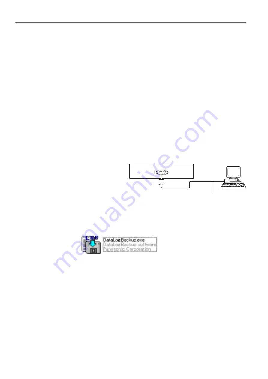
1. 4. 2. Connection preparations

1.  Confirm the projector's ID, baud rate, parity and take a 

memo.

2.  Connect the serial terminals on the projector and the PC 

by using a communication cable.

Note: 

Set up your computer not to turn in the standby or shut-

down during the work.

1. 4. 3. Backup the EEPROM data (before board replacing)

1. Set the projector to "Normal-Standby" mode (POWER indicator is Lighting in red).

2. Start up service software "DataLogBackup.exe" with a computer.

Communication cable (straight)

D-Sub 9p (Male)

D-Sub 9p (Female)

Projector Connection terminals

Computer

Summary of Contents for PT-EW730T

Page 1: ...L PT EW730Z PT EW730ZL PT EW730ZD PT EW730ZLD PT EW730T PT EW730TL PT EX800Z PT EX800ZL PT EX800ZD PT EX800ZLD PT EX800T PT EX800TL Panasonic Corporation 2013 Unauthorized copying and distribution is a violation of law LCD Projector ORDER NO VED1311485CE D10 Rev 11 2017 10 ...

Page 2: ...er When you unavoidably use lead solder use lead solder after removing lead free solder Or be sure to heat the lead free solder until it melts completely before applying lead solder After solder to double layered P C Boards check the component side for excess solder which may flow onto the opposite side About the identification of the lead free solder P C Board For the P C Board which applies lead...

Page 3: ...g SECTION 2 DISASSEMBLY PROCEDURES 1 Parts Locations 2 Mechanical and Electrical Parts Disassembly 3 Optical Parts Disassembly Cable reforming SECTION 3 ADJUSTMENTS 1 Adjustment item and a procedure 2 Software Update Procedure SECTION 4 SCHEMATIC DIAGRAM 1 Block Diagram 2 Interconnection Block Diagram 3 Schematic Diagram 4 Circuit Boards Diagram SECTION 5 PARTS LIST 1 Exploded views 2 Replacement ...

Page 4: ...Connect M1 to T1 according to Fig 2 and measure the voltage 4 Change the connection of M1 from T1 to T2 and measure the voltage again 5 The voltmeter must read 0 375 V or lower in both of steps 3 and 4 This means that the current must be 0 75mA or less 6 If the reading is out of the above standard the projector must be repaired and rechecked before returning to the customer because of a possibilit...

Page 5: ...o ON and LAMP POWER is set to AUTO Color system 7 standards NTSC NTSC4 43 PAL PAL N PAL M SECAM PAL60 Projected image size 1 02 m 40 10 16 m 400 Screen aspect ratio PT EZ770Z PT EW730Z 16 10 PT EX800Z 4 3 Projection method FRONT CEILING FRONT FLOOR REAR CEILING REAR FLOOR Speaker 3 7 cm round x 1 Max effective audio output 10 W monaural Power cord length 3 0 m 118 1 8 Outer case Molded plastic Dim...

Page 6: ...ntal 45 kHz Vertical 60 Hz f 1125 1035 60i Horizontal 33 75 kHz Vertical 60 Hz f 1125 1080 50i Horizontal 28 13 kHz Vertical 50 Hz f 1125 1080 24sF Horizontal 27 kHz Vertical 48 Hz f 1125 1080 30p Horizontal 33 75 kHz Vertical 30 Hz f 1125 1080 50p Horizontal 56 25 kHz Vertical 50 Hz f 625i 576i Horizontal 15 63 kHz Vertical 50 Hz f 625p 576p Horizontal 31 25 kHz Vertical 50 Hz f 750 720 50p Horiz...

Page 7: ...BPR signal Y 1 0 V p p including synchronization signal PBPR 0 7 V p p 75 Ω DVI D IN terminal 1 set DVI D 24 p single link DVI 1 0 compliant HDCP compatible HDMI IN terminal 1 set HDMI 19 pin HDCP compatible Deep Color compatible Audio signal Linear PCM Sampling frequency 48 kHz 44 1 kHz 32 kHz VIDEO IN terminal 1 set pin jack 1 0 V p p 75 Ω DisplayPort IN terminal 1 set DisplayPort 20 pin HDCP co...

Page 8: ...8 PREFACE ...

Page 9: ... Service Mode INF 11 3 1 Setting to Service Mode 3 2 Resetting to User Mode 3 3 Functions of Service Mode 4 External Controls INF 16 4 1 Control through Serial terminal 4 2 Control through LAN terminal 4 3 Control commands List 5 Notes on service INF 21 5 1 Before service operation 5 2 Service 5 3 Replacement of consumable parts 5 4 Initialization for control device password 6 Troubleshooting INF ...

Page 10: ... 11 15 12 14 13 15 17 9 16 10 Front Side Rear Projection direction WARNING Keep your hands and other objects away from the air exhaust port f Keep your hands and face away f Do not insert your fingers f Keep heat sensitive objects away Heated air from the air exhaust port can cause burns injury or deformations 1 Remote control signal receiver front 2 Power indicator ON G STANDBY R Displays the sta...

Page 11: ...ed to select items in the menu screen change settings and adjust levels Also used to enter a password in SECURITY or enter characters Chapter 1 Preparation About your projector 20 21 18 19 Projection direction Bottom Top 18 Burglar hook port Attaches a burglar prevention cable etc 19 Luminance sensor x page 68 20 Lens release button 21 Lamp cover The lamp unit is inside Attention f Do not block th...

Page 12: ...e terminal to input RGB signals or YCBCR YPBPR signals 6 RGB 2 IN R PR VIDEO G Y B PB C SYNC HD VD terminal This is the terminal to input RGB signals or YCBCR YPBPR signals Y C signals and video signals 7 DVI D IN terminal This is the terminal to input DVI D signals 8 DisplayPort IN terminal This is the terminal to input DisplayPort signals 9 VIDEO IN terminal This is the terminal to input video s...

Page 13: ...all the projectors with a single remote control when using multiple projectors x page 30 11 ECO button Displays the setting screen relating to ECO management x pages 57 89 12 SHUTTER button Used when temporarily turning off the image and audio x page 53 13 AUTO SETUP button Automatically adjusts the image display position while the image is projected PROGRESS is displayed on the screen while adjus...

Page 14: ...URE POSITION ADVANCED MENU DISPLAY LANGUAGE DISPLAY OPTION PROJECTOR SETUP P IN P TEST PATTERN SIGNAL LIST SECURITY NETWORK MENU SELECT SUB MENU ENTER 2 Press as to select an item from the main menu f The selected item is highlighted in yellow MAIN MENU PICTURE POSITION ADVANCED MENU DISPLAY LANGUAGE DISPLAY OPTION PROJECTOR SETUP P IN P TEST PATTERN SIGNAL LIST SECURITY NETWORK MENU SELECT SUB ME...

Page 15: ... OPTION menu ON SCREEN DISPLAY OSD DESIGN The selected item is displayed with the yellow cursor by the factory default Resetting adjustment values to the factory defaults If the DEFAULT button on the remote control is pressed the values adjusted in the menu items are restored to the factory default settings button 1 Press the DEFAULT button on the remote control 0 CONTRAST ADJUST Note f You cannot...

Page 16: ...67 SHARPNESS 6 1 67 NOISE REDUCTION OFF 67 IRIS OFF 1 67 DAYLIGHT VIEW AUTO 68 SYSTEM SELECTOR YPBPR 1 68 1 Depends on the signal input Note f The factory default settings may vary depending on the picture mode POSITION Sub menu item Factory default Page SHIFT 70 ASPECT NORMAL 1 70 ZOOM 71 CLOCK PHASE 0 1 72 KEYSTONE 72 1 Depends on the signal input ADVANCED MENU Sub menu item Factory default Page...

Page 17: ... CAPTION SETTING 83 BACK COLOR BLUE 84 STARTUP LOGO DEFAULT LOGO 84 SHUTTER SETTING 84 P TIMER 85 FREEZE 86 DIGITAL ZOOM 1 5 86 PROJECTOR SETUP Sub menu item Factory default Page PROJECTOR ID ALL 88 PROJECTION METHOD FRONT FLOOR 88 ECO MANAGEMENT 89 SCHEDULE OFF 90 STARTUP INPUT SELECT LAST USED 92 RS 232C 92 REMOTE2 MODE DEFAULT 94 FUNCTION BUTTON 94 AUDIO SETTING 94 STATUS 96 DATE AND TIME 97 SA...

Page 18: ...ORK Sub menu item Factory default Page DIGITAL LINK MODE AUTO 109 DIGITAL LINK SETUP 109 DIGITAL LINK STATUS 110 NETWORK SETUP 110 NETWORK CONTROL 111 NETWORK STATUS 111 DIGITAL INTERFACE BOX 111 Note f Some items may not be adjusted or used for certain signal formats to be input to the projector The menu items that cannot be adjusted or used are shown in black characters and they cannot be select...

Page 19: ...User Mode 1 Press the MENU button on the control panel of the projector or on the remote controller to display the main menu 2 Select a sub menu service password of the main menu projector setup and press the ENTER button 3 Input the password 0000 by remote controller and press the ENTER button 4 Press the MENU button USER MODE MAIN MENU will be displayed 3 3 Functions of Service Mode Function var...

Page 20: ... temporarily not memorized OFF Disable the Window Edge Correction Default setting 8 SGM Factory use only To switch the LCD panel gamma characteristic ON Enable the SGM function OFF Disable the SGM function Default setting 1 MODEL Model no S N Serial no 2 MAIN Main software version NT Network software version 3 SUB Sub software version DIGITAL LINK Digital Link software version 4 Emulate setting Ve...

Page 21: ...otion picture is not stabled at RGB input ȡȤȶȡȮȣȥȤȀȭȥȮȵ ȤȩȧȩȴȡȬȀȣȩȮȥȭȡȀȲȥȡȬȩȴȹ ȢȬȡȮȫȩȮȧ ȯȮ ȒȔ ȩȮȰȵȴȀȲȥȳȯȬȵȴȩȯȮ ȣȬȡȭȰȀȰȯȳȩȴȩȯȮ ȦȲȡȭȥȀȬȯȣȫ ȲȡȳȴȥȲȀȰȯȳȩȴȩȯȮ ȭȥȮȵȀȳȥȬȥȣȴ ȣȨȡȮȧȥ 3 PROJECTOR SETUP menu The special items are added as shown below on the EMULATE of RS232C menu MODE NE other companies MODE MI other companies MODE EP other companies MODE SO other companies MODE SA other companies OTHER other ...

Page 22: ...s Rotational speed EXHST Exhaust fan status Rotational speed 4 Page 6 LAMP HISTORY Lamp On Off status history log ȳȴȡȴȵȳ ȕȏȖ ȴȥȭȰȈºCȉ ȶȯȬȴ ȰȀȭȯȤȥ ȦȡȮȀȭȯȤȥ ȡȴȭ ȬȣȤȀȲ ȬȣȤȀȢ ȬȭȰȀȑ ȰȯȷȥȲ ȳȥȮȤȀȳȴȡȴȵȳȀȶȩȡȀȥȍȭȡȩȬ ȣȨȡȮȧȥ ȥȮȴȥȲ ȥȸȩȴ ȭȥȮȵ ȒȒȎȓȈȩȮȉȏȀȓȔȎșȈȯȵȴȉ ȗȗȎȗ Ȥȥȳȫ ȐȕȐȎȗ ȑȒ ȯȫȻȑșȖȔɒɐɍȽ ȯȫȻȒȐȖȔɒɐɍȽ ȯȫȻȑȗȓȑɒɐɍȽ ȣȬȯȧ ȡȰȬ ȬȣȤȀȧ ȰȢȳ ȬȭȰȀȒ ȥȸȨȳȴ Ȭȯȷ ȑȐȑȗȎȗȏȀȓȔȎȘ ȯȫȻȑșȓȑɒɐɍȽ ȯȫȻȑșȕȔɒɐɍȽ ȯȫȻȒȑȓȑɒɐɍȽ ȯȫȻȑȒȔȓɒɐɍȽ ...

Page 23: ...L QUALITY is added to sub menu DIGITAL LINK STATUS CHANNEL A Signal information of channel A CHANNEL B Signal information of channel B CHANNEL C Signal information of channel C CHANNEL D Signal information of channel D ȩȮȩȴȩȡȬȩȺȥ ȡȬȬȀȵȳȥȲȀȤȡȴȡ ȲȥȧȩȳȴȥȲȥȤȀȳȩȧȮȡȬ ȮȥȴȷȯȲȫȏȥȍȭȡȩȬ ȬȯȧȯȀȩȭȡȧȥ ȳȨȵȴȴȥȲȀȣȯȵȮȴȥȲ ȭȥȮȵȀȳȥȬȥȣȴ ȥȸȥȣȵȴȥ ȥȮȴȥȲ ȩȮȩȴȩȡȬȩȺȥȀȳȨȵȴȴȥȲȀȣȯȵȮȴȥȲȟ ȥȸȥȣȵȴȥ ȣȡȮȣȥȬ ȣȨȡȮȧȥ ȥȸȥȣȵȴȥ ȥȮȴȥȲ Ȥȩȧȩȴȡ...

Page 24: ...ible device set the PROJECTOR SETUP menu ECO MANAGEMENT STANDBY MODE to NORMAL to control the projector in standby mode When STANDBY MODE is set to ECO the projector cannot be control during standby 4 1 2 Pin assignments and signal names D Sub 9 pin female Outside view Pin No Signal name Details 9 6 5 1 1 NC 2 TXD Transmitted data 3 RXD Received data 4 NC 5 GND Earth 6 NC 7 CTS Connected internall...

Page 25: ...r Adds the value specified by the parameter to the current value 5 Sign Specifies the method of processing the value specified by parameters Code Description The value specified by the parameter is a positive value or 0 zero The value specified by the parameter is a negative value 6 Parameters Specify the setting or adjustment value by right justification 0 is not suppressed For example when the s...

Page 26: ...N cable straight LAN cable straight Hub Note Lan cable and Hub are not standard accessories When connected directly cross type cable is recommended 4 2 2 When Web control administrator rights password is set Protect mode 4 2 2 1 Connecting 1 Obtain the IP address and port number Initial setting value 1024 of the projector and request for a connection to the projector You can obtain both the IP add...

Page 27: ...arameter range ERR3 Busy state or no acceptable period ERR4 Timeout or no acceptable period ERR5 Wrong data length ERRA Password mismatch CR 0x0d 4 byte 1 byte Example Query Power QPW 1 Connects to the projector IP 192 168 0 8 port 1024 2 Receives a response Response NTCONTROL 1 1aa6c14e CR 1aa6c14e 8 bytes random characters 3 Generates a hash value message digest from admin1 panasonic 1aa6c14e by...

Page 28: ...following command formats Transmitted data Header Data section Termination symbol 0 0x30 0 0x30 Control command ASCII string CR 0x0d 1 byte 1 byte Undefined length 1 byte Received data Header Data section Termination symbol 0 0x30 0 0x30 Control command ASCII string CR 0x0d 1 byte 1 byte Undefined length 1 byte Error response Error message Termination symbol ERR1 Undefined control command ERR2 Out...

Page 29: ...nd its replacement cycle Make sure to replace the lamp unit regularly Refer to items When to replace the lamp unit How to replace the lamp unit If the lamp bursts gas contained inside of the lamp is released in the form of smoke It is recommended that you store the Replacement Lamp Unit as a contingency Replacement lamp unit ET LAE300 Note Panasonic takes no responsibility for any damage or malfun...

Page 30: ...e static electricity of clothes or human body Please take care in static electricity use an antistatic wrist strap or wear the anti static electricity gloves 3 After repairing please check the gradation 10step or the gray scale test pattern or moving image Also please check that it is normal on a self check screen 5 2 3 Interlock detection The lamp cover switch detects whether the lamp cover is mo...

Page 31: ...turns off automatically after approximately 10 minutes as it may cause malfunction of the projector Note To predict when to replace the lamp check the lamp runtime displayed at LAMP TOTAL in STATUS 3 000 hours is only the target for replacement and not the warranty time 5 3 2 Calculation formula of lamp runtime The lamp runtime that is displayed in the STATUS is real time The following conversion ...

Page 32: ... not installed properly remove it and then push it in slowly Push ing it in quickly or forcibly may break the connector 1 Set the MAIN POWER switch to OFF and disconnect the power plug from the power outlet Wait at least one hour and check if the lamp unit has cooled down 2 Remove the lamp cover Fig 1 Use a Phillips screwdriver to turn the lamp cover fixing screw x1 counterclock wise until it turn...

Page 33: ...r unit from the tabs of the projector while slightly pressing the tab at the center of the frame at the con necting terminal side rear side inward as shown by the arrow and remove the air filter unit Fig 2 After pulling out the air filter unit remove foreign objects and dust from the air filter unit compartment and the projector s air intake port if there are any Fig 3 Fig 4 Fig 5 3 Wash the air f...

Page 34: ...it back to the projector Attaching a wet unit will cause an electric shock or malfunction Do not disassemble the air filter unit Make sure that the air filter unit is properly attached before using the projector If it is not attached the projector will suck in dirt and dust causing a malfunction Note If you use the projector without attaching the air filter unit the filter indicator FILTER flashes...

Page 35: ...or Disconnection Fan rotation error Each FAN sense signal a Fan rotation is slower than 70 of target for more than 5 seconds Fan rotation error TEMP LED blinks 2 times TEMP LED lights Intake air temperature sensor a Higher than 48ºC Higher than 43ºC at highland mode Intake air temperature error Filter clogging High temperature of environment Ventilation holes are blocked 46ºC High altitude 41ºC a ...

Page 36: ...te of Projector ID and Transmission speed Parity setting 2 Connect the serial terminals on the projector and the PC by using a communication cable Attention Please setup the computer not into standby or shutdown during the working 6 2 3 Acquisition of log data 1 Switch the projector to Normal Standby mode POWER indicator is Lighting in red 2 Start up service software DataLogBackup exe with a compu...

Page 37: ...INF 29 SECTION 1 SERVICE INFORMATION 5 Select Log SYSTEM and click Get button 6 Log is displayed ...

Page 38: ...000000 20000000 Lamp cover not installed securely Lamp cover is not installed securely 30 00000000 40000000 Not used 31 00000000 80000000 Not used 32 0000000100000000 Intake air temperature sensor disconnected Intake air temperature sensor disconnected 33 00000002 00000000 Not used 34 00000004 00000000 Exhaust air temperature sensor disconnected Exhaust air temperature sensor disconnected 35 00000...

Page 39: ...ed more than 15º 96 00000001 00000000 Not used 97 00000002 00000000 Not used 98 00000004 00000000 Sub microprocessor communication error Communication error on sub microprocessor 99 00000008 00000000 IIC communication error 1 RTC Device operation failure on signal processing part 100 00000010 00000000 IIC communication error 2 EEPROM 101 00000020 00000000 IIC communication error 3 LAMP1 EEPROM 102...

Page 40: ...t between pins 5 8 10 8 14 15 of connector A15 and pins 2 5 of connector A17 NG A Replace the A P C Board Confirm the lamp condition NG Replace the lamp Is each thermal sensor operating in normal NG Check each thermal sensor and connection A Confirm that the short circuit between pins 1 and 3 of connec tor K9201 DC 380V is observed in normal NG A Check or replace P P C Board Is each fan rotating w...

Page 41: ...ges between pins of connector B1 below 1 3 DC 380V 4 3 DC 18V NG B Check or replace B P C Board B Confirm the short circuit of Q9611 Q9612 Q9615 Q9602 Q9603 NG B Replace the shorted parts P Confirm that the short circuit between pins 4 and 3 of connec tor K9201 DC 18V is observed in normal NG P Check or replace P P C Board OK OK OK OK ...

Page 42: ...k No picture with all of inputs A Check each power supply voltage of microprocessor resize IC IC1102 FPGA IC1103 LCD IC IC1104 panel driver IC IC1105 IC1107 NG A Check IC1110 IC1045 IC1049 IC1052 IC1066 IC1068 IC1075 IC1077 and peripheral circuits A Check the waveform LDVS output clock at R2502 R2508 of IC1103 FPGA NG A Check IC1103 FPGA and peripheral circuit A Check the waveform at IC1105 IC1107...

Page 43: ...C1120 B Pb NG A Check C1118 C1119 C1120 and peripheral circuit J Check the waveform at pin 26 of JK4007 NG J Replace J P C Board One of the inputs DVD I DIGITAL LINK can be displayed NG A Check IC1100 and peripheral circuits A Check the output waveform at L1323 L1324 L1325 NG A Check L1323 L1324 L1325 and peripheral circuit A Check IC1102 and peripheral circuits A Check IC1100 and peripheral circu...

Page 44: ...14 C1115 C1116 and peripheral circuit One of the inputs DVD I DIGITAL LINK can be displayed NG A Check IC1100 and peripheral circuits DisplayPort input can be displayed NG A Check IC1016 and peripheral circuits A Check the output waveform at L1320 L1321 L1322 NG A Check L1320 L1321 L1322 and peripheral circuit A Check IC1100 and peripheral circuits Check JK1006 and peripheral circuits One of the i...

Page 45: ...e points below R3014 DPRX_HPD_OUT Pin130 and 131 of IC1016 TMDS_CLK_N TMDS_CLK_P A Check IC3001 and peripheral circuits A Check the output waveform of IC1016 at the points below R1332 FB_HD FB_VD FB_ACT R1311 FB_PICLK R1313 FB_G9 A Check IC1016 and peripheral circuits One of the inputs VIDEO S VIDEO RGB1 RGB2 HDMI can be displayed NG A See A P C Board operation check A Check L1019 L1020 JK1004 and...

Page 46: ...A Check the voltages DC 3 3V at pins 11 18 29 and 55 of IC1030 SUB CPU NG A Check IC1030 and peripheral circuits A Check the voltage DC 1 2V at L1079 NG A Check IC1045 and peripheral circuits A Check the voltage DC 3 3V at pin 1 of IC1031 RESET NG A Check IC1031 and peripheral circuits A Check IC1043 FLASH ROM and peripheral circuit NG A Check IC1102 CPU RESIZE and peripheral circuits A Check the ...

Page 47: ...al circuits A Check the cable connection of JK4005 SERIAL IN NG A Connect the connector securely A Check the cable connection between V1 A27 NG Replace the cable A The signal waveform can be detected at pins 13 15 and 17 of IC4002 when the serial command is transmitted NG A Check IC4002 and peripheral circuits A Check the waveform at L1182 when the remote control button is pressed NG V Replace V P...

Page 48: ...en the contact controller is used NG A Replace J P C Board A Check the connection cable between A32 S1 NG Replace the cable A Check the FPC cable between JK4007 A28 NG Replace the FPC cable A Check the voltage DC 3V at pins 9 12 of connector S1 NG S Check the 3 3V power line on the S P C Board A The signal waveform can be detected at L1194 L1197 L1202 L1203 L1205 L1206 NG J Replace J P C Board A C...

Page 49: ...Check the cable connection between connectors A28 JK4007 NG Replace the cable S Common Check the waveform at pins 5 and 10 of IC1029 NG A Check IC1016 IC1100 and peripheral circuits A Common Check the waveform at pins 2 and 13 of IC1029 NG A Check IC1029 and peripheral circuits A Replace A P C Board OK NG NG NG OK OK OK OK Check each cable connection No sound with built in speaker Follow the secti...

Page 50: ... Check the waveform at pins 1 and 3 of connector A1 NG A Check IC1028 and peripheral circuits A ANALOG Check the connection cable between connectors A28 and JK4007 NG A Replace cable A Replace speaker J Replace J P C Board A Replace A P C Board A Replace A P C Board OK OK OK OK ...

Page 51: ...l 2 4 Lamp and lamp cover removal 2 5 Top cover removal 2 6 V P C Board A J P C Board assy removal 2 7 Front cover removal 2 8 Lighting assy removal 2 9 Exhaust and lamp fans removal 2 10 Lamp house thermal fuse removal 2 11 S P C Board assy removal 2 12 Power box removal 2 13 Filter house removal 2 14 Intake duct assy removal 2 15 Panel fans removal 3 Optical Parts Disassembly DIS 16 3 1 Disassem...

Page 52: ...ower fan Lamp fan 2 Lamp fan 1 PBS fan Exhaust fan Board name Function summary Board name Function summary A Image processingsystem CPU P Power supply J Signal input terminals BQ Ballast power Ballast control S Control panel K AC inlet V Status LED IR receiver M1 Temperature sensor Intake air M2 Temperaturesensor Exhaust air M3 Air flow sensor F Filter switch detection C Lamp memory connection ...

Page 53: ...ilter unit Filter house Top cover Lighting block Lamp cover Rear panel G Polarizer R Polarizer Shutter unit Iris unit Lens shift unit Projection lens Optical block B Polarizer Lighting case top Lighting case bottom PBS Integrator lens out Integrator lens in Lamp unit Power box Control buttons Bottom case Lens shift cover bottom Lens shift cover Top Front cover ...

Page 54: ...t reusing it on the occasion of assembling 2 12 Power box removal 2 15 Panel fans removal 2 13 Filter house removal 2 14 Intake duct assy removal Cable reforming 2 12 Fans FN906 FN909 FN910 removal 2 11 S P C Board assy removal 2 10 Lamp house thermal fuse removal 2 9 Exhaust and lamp fans removal 2 8 Lighting assy removal 2 7 Front cover removal 2 6 V P C Board A J P C Board assy removal 2 5 Top ...

Page 55: ...nterclockwise gently to the end and take it out Projection lens Lens release button Red point marker Attaching the lens 1 Align the red mark on the Projection Lens with the red mark on the projector and insert the Projection Lens as far as possible 2 Turn clockwise to the end Note Do not press the lens release button when attaching the lens ...

Page 56: ...2 Unhook the hook of air filter and take it out 2 4 Lamp and lamp cover removal 1 Loosen 1 screw A and open the lamp cover to slide it in the arrow direction 2 Loosen 3 screws B on the lamp and pull it upward off A A Air filter Lamp Lamp cover Filter cover B A SMXAA309R0SAD 4120796409 B THEL110J A SMXAA309R0SAD 4120796409 ...

Page 57: ...op cover assy Prism cover A B B B B B B B B B B B B 2 5 Top cover removal 1 Loosen 1 screw A and slide the prism cover in the direction and open it 2 Remove 12 screws B and take the top cover assy upward A SMXAA309R0SAD 4120796409 B XSB3 8FN ...

Page 58: ...J P C Board E E F F G H J J H 2 6 V P C Board A J P C Board assy removal 1 Remove 4 screws A and remove V P C Board 2 Remove 1 screw B and 6 screws C and 1 screw D and remove A J P C Board assy upward off A XYN3 F8FJ B XYC3 FG12FN C XYN3 F12FJ D XSB3 8FN E THEC198N F J XYN3 F8FJ G XTB3 8GFJ H XSB3 8FN ...

Page 59: ...DIS 9 SECTION 2 DISASSEMBLY PROCEDURES A A A A A A Front cover assy 2 7 Front cover removal 1 Remove 6 screws A and remove the front cover assy A XTB3 8GFJ ...

Page 60: ... C C C Lighting case D D D D A C XTB3 8GFJ B XYC4 FG12FJ 2 8 Lighting assy removal 1 Remove 2 screws A and remove lens cover top 2 Remove 4 screws B and remove lighting assy upward 3 Remove 3 screws C and remove lens cover bottom D XYN3 F12FJ E SMSDN3014SV 4111898308 Lens shift assy Lens mount E E E ...

Page 61: ... Lamp fan 2 Lamp fan 1 M2 P C Board Exhaust fans assy 2 9 Exhaust and lamp fans removal 1 Remove 3 screws A and remove the exhaust fan assy 2 Remove 3 screws B and remove the lamp fan assy 3 Remove 3 screws C and remove the PBS duct 4 Remove 2 screws D and remove the PBS fan A XYC3 FG12FN B C XTB3 8GFJ D E XTB3 12GFJ ...

Page 62: ...use 2 10 Lamp house thermal fuse removal 1 Remove 2 screws A and remove C P C Board 2 Remove 1 screw B and remove the ballast socket 3 Remove 3 screws C and remove the lamp house cover 4 Remove 1 screw D and remove the thermal fuse assy A D XTB3 8GFJ B SFPAY30100SV 4111926303 C XTB3 12GFJ E XYC3 FG12FN 2 11 S P C Board assy removal 1 Remove 2screws E and remove S P C Board assy upward ...

Page 63: ...uct B B B A A A Power fan BQ P C Board K P C Board P P C Board C C D E E E E E E E 2 12 Power box removal 1 Remove 3 screws A and remove the power duct 2 Remove 3 screws B and remove the Power box A XTB3 8GFJ B XYC3 FG12FN C XYN3 F30FJ D XYN4 E8FJ D XYN3 F8FJ ...

Page 64: ...C Board Ribs Rib 2 13 Filter house removal 1 Remove 1 screws A and 2 screws B and remove the filter house assy upward 2 14 Intake duct assy removal 1 Remove 4 screws A and remove the earth bracket 2 Remove 2 screws B and remove the dust sheet 3 Remove 6 screws C and remove the intake duct assy upward A XTB3 8GFJ B XSB3 8FN A XYC3 FG12FN B C XTB3 8GFJ ...

Page 65: ...t top Intake duct bottom Panel fan 1 Panel fan 2 Panel fan 3 2 15 Panel fans removal 1 Remove 2 screws A and remove the intake duct top 2 Remove 2 screws B and remove the panel fan 1 3 Remove 6 screws C and remove the panel fan 2 and 3 A XTB3 8GFJ B XTB3 12GFJ C THTA073J ...

Page 66: ...mp cover prism cover removal Completed Product 3 2 Shutter unit removal 3 3 Optical block removal 2 5 Top cover removal 3 4 Polarizer in removal 3 3 1 Polarizer out removal 3 5 Iris Integrator lens assy removal 3 6 Parts location and direction in the lighting case 2 6 V P C Board A J P C Board removal ...

Page 67: ...en replacing the LCD panel should be replaced whole of the LCD panels and prism assy at once When replacing optical block take the optical and electrical adjustments following to the chapter Adjustment Shutter unit Optical block A B B B 3 2 Shutter unit removal 1 Loosen 1 hex screw A by the hex wrench M2 and remove the shutter unit upward 3 3 Optical block removal 1 Loosen 3 hex screws B by the he...

Page 68: ...ver grasp the surface or edges of the polarizer with bare hand If fat and oil on your hand adheres on the edges of polarizer the linear bolt may appear on the glass surface due to capillarity Grasp the edges of the glass with new gloves or with tweezers when handling it l Inorganic polarizer cleaning When removing the dust on the surface use a commercial inert gas air spray or air blower to remove...

Page 69: ...r Marker D D D Mount the polarizer as the marker comes on the top right viewing from the light in coming side 3 4 Polarizer in removal 1 Remove each 1 screw D on the polarizing stopper and re move the stopper and polarizer in assy upward carefully D XYN2 F8FJ Al evaporated side light out side Al evaporated side light out side Al evaporated side light out side ...

Page 70: ...sy Light shield bracket A B B A A A A Iris unit PBS Cut corner Integrator out Integrator in C C C D 3 5 Iris Integrator lenses assy removal 1 Remove 5 screws A and remove the lighting case cover 2 Remove 2 screws B and remove the iris integrator lenses assy upward A B C SFXAA308R0SAD 3120694708 D XYN2 F8FJ ...

Page 71: ...eflection side Coated side comes reflection side Marking comes this side up Marking comes this side up 3 6 Parts location and direction in the lighting case When mounting or assembling the parts in the lighting case the parts must be mounted in the speci fied location and direction as shown in the figure below Note The parts indicated with are mounted by adhesive therefore they cannot be replaced ...

Page 72: ...2 C1 Ferrite core Ferrite core Ferrite core Connector Connect to A8 PBS fan A22 Iris unit A32 S P C Board A6 Lamp fan 2 A21 Lens shift unit Connector Connect to A19 Shutter unit A20 Lens mount unit A1 Speaker A27 V P C Board A9 Panel fan 1 A4 Panel fan 2 A12 M1 P C Board A13 M3 P C Board Connector Connect to A23 F P C Board A5 Panel fan 3 A2 Power fan A17 P P C Board A15 P P C Board Connector Conn...

Page 73: ...gence Adjustment 1 3 Flicker Adjustment 1 4 EEPROM data transfer 1 5 Gamma Color uniformity correction data transfer 1 6 Model Information Setup 1 7 Clog sensor calibration 1 8 Date and time setting 2 Software Update Procedure ADJ 11 2 1 Update by the LAN terminal connection Main sub network software updating 2 2 Update by the serial terminal connection Main sub DIGITAL LINK software updating Rev ...

Page 74: ...y correction data transfer A P C Board Transfer the data from old A P C Board to new one 1 6 Model information setup A P C Board Not necessary when the item 1 4 EEPROM data transfer was taken 1 7 Clog sensor calibration A P C Board Z P C Board 1 8 Date and time setup A P C Board 1 1 Polarizer adjustment 1 1 1 Preparation 1 Loosen the screw A on the lamp cover and slide it until the screw B on the ...

Page 75: ...Electrical Convergence Adjustment This is a function to correct a convergence by a pixel unit every R G B ingredient Each pixel can be shifted in 1 dot and 2 dots maximum from right to left and up and down 1 Project cross hatch pattern confirm a position gap of R G B 2 Enter the service mode and select sub menu CONVERGENCE of main menu EXTRA OPTION 3 Select a color to be adjusted 4 Press the butto...

Page 76: ... MENU button to close the adjustment The adjustment data will be saved in the memory 1 4 EEPROM data transfer 1 4 1 Equipment to be used 1 Computer Use it for the transfer of backup data 2 Communication cable D sub 9pin male female RS 232C straight 3 Service Software DataLogBackup exe Service software is downloaded from the projector service homepage 1 4 2 Connection preparations 1 Confirm the pro...

Page 77: ...USTMENTS 3 Select Option Setting and set Serial Port of the computer Baud Rate and Parity 4 Select a model number and ID 5 1 Select Backup EEPROM tab 2 Check REPLACE A PWB of COPY MODE item 3 Click the READ EEPROM button ...

Page 78: ...TMENTS 6 Select the save place and set the file name and click the Save S button 7 When the progress bar reaches the right side end the data reading out and saving process are complete Select File Quit to quit the software ...

Page 79: ... of the computer Baud Rate and Parity 4 Select a model number and ID 5 1 Choose Backup EEPROM tab 2 Check the REPLACE A PWB of COPY MODE item 3 Click the WRITE EEPROM button 6 Select the backup file and click the OPEN O button 7 When the progress bar reaches the right side end the data writing process is complete Select File Quit to quit the software 8 After finishing the data writing turn the POW...

Page 80: ... before board replacing 1 Set the projector to Normal Standby mode POWER indicator is Lighting in red 2 Start up the software ServiceEZ770 exe with a PC 3 Select language and click the OK button 4 1 Choose the available serial port number on your PC 2 Choose a model number 3 Click the Data button 5 1 Click the Reception button of Gamma Data 2 Select the save place and click the Save S button 3 Whe...

Page 81: ... port number on your PC 2 Choose a model number 3 Click the Data button 5 1 Click the Transmission button of Gamma Data 2 Select the save place and click the Open O button 3 When the progress bar reaches the right side end the transmission of data is completion 4 Restore the Uniformity correction data in the same procedure of 1 3 6 After completing the writing turn the main power off and on and ch...

Page 82: ... object to block the exhaust air 1 Enter the service mode and select sub menu CLOG SENSOR CALIBRATION of main menu EXTRA OPTION 2 Select OK and press ENTER button to start the calibration 3 After approx 15 minutes the calibration is complete and the white screen switches to normal screen Turn the POWER switch off and on and then confirm that the projector operates correctly The lamp power mode swi...

Page 83: ...mep age 4 Microprocessor software Please download the file from the projector service homepage to your PC 2 1 2 Connection Preparations 1 Set the DIGITAL LINK MODE of the NETWORK menu of projector to AUTO or ETHERNET 2 Confirm the network IP address of the projector and take a note 3 Set the IP address of computer to the same IP address group of the projector Note Set up your computer not to turn ...

Page 84: ...ton which you want to update the software 6 Select the new software and click Open button 7 After getting the software a checkmark and path name to the software and a version will be displayed on the window Click the Update button to start updating of the software If you do not want to update the software uncheck the software DIGITAL LINK software cannot be updated by the network connection ...

Page 85: ...en turn the projector on Confirm whether the version of the Microprocessor Software is updated definitely with sub menu STATUS of the main menu PROJECTOR SETUP During updating the progress window will appear and the LED indicators on the projector will light as the below Main LAMP and TEMP indicators flash in red alter nately Sub POWER indicator is off LAMP and TEMP indica tors light in red Networ...

Page 86: ... from the projector service homepage to your PC 2 2 2 Connection Preparations 1 Set the RS232C of the PROJECTOR SETUP menu to PROJECTOR 2 Confirm the Projector s ID Baudrate and Parity and take a note 3 Connect the serial cable Note Set up your computer not to turn in the standby or shutdown during the software updating 2 2 3 Update procedure 1 Set the projector to Normal Standby mode POWER indica...

Page 87: ...ng in step 3 5 Click the load button which you want to update the software 6 Select the new software and click Open button 7 After getting the software a checkmark and path name to the software and a version will be displayed on the window Click the Update button to start updating of the software If you do not want to update the software uncheck the software ...

Page 88: ...en turn the projector on Confirm whether the version of the Microprocessor Software is updated definitely with sub menu STATUS of the main menu PROJECTOR SETUP During updating the progress window will appear and the LED indicators on the projector will light as the below Main LAMP and TEMP indicators flash in red alter nately Sub POWER indicator is off LAMP and TEMP indica tors light in red Networ...

Page 89: ...esistors unless marked as follows The unit of resistance is an OHM Ω K 1 000 M 1 000000 Nonflammable Metal Oxide Solid Metal Film Wire Wound Fuse 2 Capacitor Temperature Compensation Electrolytic Polyester Bipolar Metallized Polyester Dipped Tantalum Polypropylene Z Type 3 Coil The unit of inductance is a H unless otherwise noted 4 Test Point Test Point 5 HOT and COLD indications The power circuit...

Page 90: ...ONTROL IC 18V 380V Q9201 Q9202 Q9204 PFC CONTROL K9006B LINE FILTER HOT COLD 1 5 3 PHOTO ISOLATOR PC9204 5 CPU IC9701 Q5 Q2 B1 1 4 HALF BRIDGE DRIVER HALF BRIDGE DRIVER IGNITER BLOCK B5 B6 18V B2 380V STEP DOWN CHOPPER Q9602 Q9603 D9629 D9630 L9603 L9604 C9624 IC9610 IC9609 Q9615 Q9616 Q9611 Q9612 B P C B Q P C B COLD HOT F9602 LAMP BQ P C B 2 UART TXD UART RXD ACT LAMP ON SYNC SYNC LINE FILTER L9...

Page 91: ...NEL B PANEL G PANEL R S H WXGA 3 WXGA XGA 1 27M VCXO 512M EEPROM SUBCPU ST STM8L052R8T6 DDR2 SDRAM C3ABSY000090 DDR2 SDRAM C3ABSY000090 Wired R C R C SW SW SW Monitor Out THS7347 SW Contro LED TEMP SENSOR TEMP SENSOR FILTER SW WIND SENSOR SHUTTER DLV ZOOM FOCUS LENS SHIFT Mechanical IRIS POWER Direct Ballast Power Supply Block LAMP COVER SW LAMP Lamp Memory EEPRO CONNECTOR BD 6Pin LPF THS7314DR FP...

Page 92: ...T ADC2 7495 LENS_CH_POSI 3 OUT x3 IN x2 FPGA_CFG OUT x4 IN x1 FPGA_SO SI 4 FPGA_SI Lamp_On OUT 64Mbit Flash ROM MX29LV640ETTI 70G CPU BUS PANEL DRIVER FANCON MOTOR 6 FAN PWMOUT EP4CE10F17C8N ALTERA 2 MAIN3 3V HDBaseT Rx Valens VS100RX SW HDBT RS232C UART UART IIC LAMP 4L SEIRAL IIC IIC UART DP STDP2650 I O 8 FILTER LED FAN SENSE PWMO 2 2 2 6 LENS_CV_POSI DLV SENSE EDID RGB2 5V EDID DVI D 5V AUDIO ...

Page 93: ...1 2 3 4 5 SW1001 K0L1CA000005 SPVT110102 B1001 BCR20V4 S S NC DC380V H COM 18V V SENS IN 3 3V HOT COM FB Enable OUT FuBr Fail IN HV SENS IN 380V SENS IN 9V IN 380V RIPPLE IN FuBr POL OUT HOT COM I SENS IN PWM1H H OUT Low Hi Lamp1 Lamp2 Lamp 9V IN 380V RIPPLE IN FuBr POL OUT I SENS IN PWM1H H OUT V SENS IN 3 3V HOT COM FB Enable OUT FuBr Fail IN HV SENS IN 380V SENS IN HOT COM B to B Lamp ON OFF La...

Page 94: ...SPDIF_IN3 IC1100 D12 VS_IN IC1100 H14 AGND IC1101 V6 AVDD10 IC1100 D16 AGND IC1100 Y2 DE IC1100 AB13 P19 IC1100 R11 DVDD IC1101 K9 VSS IC1100 K20 AGND IC1100 T8 DGND IC1100 K9 CVDD IC1100 AA14 SCL IC1100 U21 LRCLK2 SPDIF_IN5 IC1100 M21 ARESETB IC1100 N9 DGND IC1100 AC19 LLC BLC IC1100 K7 CVDD IC1101 E19 PDIF_DOUT2_GPIO IC1100 V3 TVDD IC1100 L12 DGND IC1100 E3 DGND IC1100 H8 AGND IC1100 D3 TVDD IC1...

Page 95: ...N IC1102 AB17 LVDS_VDE IC1102 H26 SSTL18_VDDE IC1102 M29 MCLKO2 IC1102 F26 SSTL18_VDDE IC1102 J28 MD 25 IC1102 E3 ADC_AVS IC1102 AF25 POD 12 IC1102 G25 VSS IC1102 C6 PI2FLD IC1102 R12 VSS IC1102 C7 GIO 42 IC1102 N19 VSS IC1102 AG22 LVDSO1B 1 IC1102 C24 MULTENB IC1102 T25 VSS IC1102 C18 PI1D 11 IC1102 P1 VRHAD 2 IC1102 G30 MDQSB 2 IC1102 P2 AVS2_0 IC1102 G14 NC IC1102 C15 PI1D 24 IC1102 K25 VSS IC1...

Page 96: ...XGP4 IC1104 R3 VSU IC1104 AN27 VSS IC1104 T5 VSU IC1104 G6 VSU IC1104 P4 VSU IC1104 AJ34 PLLVDD01 IC1104 G7 VSS IC1104 D30 VSS IC1104 V21 VDDI IC1104 R6 VDU IC1104 AF5 VSU IC1104 W13 VSS IC1104 G28 VSS IC1104 V14 VDDI IC1104 R34 TXGP3 IC1104 R12 VSS IC1104 AE28 VSS IC1104 W32 UGND IC1104 W29 UGND IC1104 AA29 UGND IC1104 AH25 VSS IC1104 AN5 VSS IC1104 AH23 VSS IC1104 AN1 NC IC1104 M34 TXRP7 IC1104 ...

Page 97: ...57 4 7k R9833 100 R9835 22k R9837 100 R9838 100 R9831 100 R9828 15k 1 R9853 4 7k R9854 470 R9830 100 R9855 1M R9808 100 1 R9824 1 1k 1 R9806 15k R9856 22k R9501 56 1 R9825 15k R9844 22k R9832 1 R9818 4 7k H2C750400001 X9800 CSTCR7M50G53 R0 9V IN 380V RIPPLE IN FuBr POL OUT I SENS IN PWM1H H OUT V SENS IN 3 3V GND EMUD MCLR EMUC VDD HOT COM Vla LIMITER FuBr Fail IN HV SENS IN 9V 3 3V 380V SENS IN H...

Page 98: ...01B707 C9140 CEXLB1 V101VEJ C9248 F1J1E2 25A178 C9227 B0ACCK000005 D9205 K9006AA_1B B0JCME000012 D9314 F2A1A3920033 C9383 B0HAMR000049 D9121 B0JBSG000059 D9383 D0GB101JA089 R9389 D0GB101JA089 R9385 STB6V 7V B0JCMC000002 D9289 2 1 B0JCMC000002 D9201 2 1 J0JYB0000024 L9212 J0JYB0000024 L9213 J0JYB0000024 L9219 TTK15A50D N Q9202 G D S D0GB10 4JA068 R9201 D0GN2R2ZA008 R9251 X R9256 D0GBR00JA071 R9252 ...

Page 99: ...1991 L129 9 R2161 R2356 R2162 R1993 R2357 R2163 CL1240 R2164 CL1241 CL1242 CL1243 C2383 CL1244 CL1245 R1999 C2386 C2387 C2388 R2554 C2389 C2390 Q1004 R2174 R2368 Q1005 R2369 R2175 Q1006 R2176 C2393 Q1007 R2177 C2394 Q1008 R2178 C1200 R2179 C1201 Q1009 C2395 CL1062 C1202 C2396 CL1063 C2397 C1203 CL1064 R2370 C2398 CL1065 L3001 R2371 CL2005 CL1066 R2372 L3002 CL200 6 CL1067 CL200 7 CL1068 CL2008 Q10...

Page 100: ...L1099 CL1231 R1791 CL123 2 R1792 C2373 R1793 CL123 3 C2374 CL123 4 R1794 C2375 R1795 CL123 5 R179 6 C2376 R1797 CL123 7 R254 3 R2544 R2350 R179 8 CL104 5 R2351 R179 9 R2545 C2379 CL123 9 CL104 6 C2186 R2546 CL104 7 R2547 C2187 CL104 8 C2188 R2548 CL104 9 C2189 R2549 C2380 R2165 C2381 R1995 C238 2 R1996 R2166 R1997 R2167 CL105 0 R2550 R1998 C2190 R2168 CL105 1 C2191 R2169 R2551 CL105 2 R2552 CL105 ...

Page 101: ...9002 R9213 R9214 Q9202 C9382 D9383 L9219 L9213 L9212 R9144 1 15 K9301 4 1 K9201 1 4 3 2 PC9102 IC9203 L9104 L9311 L9314 L9315 C9335 1 5 10 7 T9152 1 3 K9006B 8 5 4 1 IC9183 K9302 SW9002 SC9308 SC9309 SC9304 C9142 D9119 D9118 K9201A_1A R9251_1 K9001A_2A T9251 4 C9219 C9220 C9221 C9222 C9224 C9228 C9229 C9231 C9232 C9234 C9243 C9250 C9254 C9255 C9256 C9280 C9292 C9294 C9295 C9225 C9245 C9246 D9206 D...

Page 102: ...6 L 9 6 3 7 L 9 6 3 8 C L 9 6 0 0 C L 9 6 0 1 C L 9 6 0 2 C L 9 6 0 3 C L 9 6 0 4 C L 9 6 0 5 C L 9 6 0 6 C L 9 6 0 7 C L 9 6 0 8 C L 9 6 1 0 C L 9 6 1 1 C L 9 6 1 2 C L 9 6 1 3 C L 9 6 1 4 C L 9 6 1 6 C L 9 6 1 9 C L 9 6 2 2 C L 9 6 2 4 C L 9 6 2 5 C L 9 6 3 7 C L 9 6 3 8 C L 9 6 3 9 Q9607 R9619 4 4 Q P C Board 4 5 J P C Board A side B side A side B side 1 2 4 3 K A K A K A K A 1 7 8 14 15 21 22 ...

Page 103: ...1 3 4 10 M1 P C Board 4 11 M2 P C Board 4 12 M3 P C Board 4 7 V P C Board A side A side A side A side B side B side B side B side PbF CF3201 M1 CL3201 CL3202 T O P 1 2 TNPA5893 PbF CL3301 CL3302 M2 CF3301 TNPA5894 T O P 1 2 PbF CF3401 M3 CL3401 CL3402 1 2 T N P A 5 8 9 5 PbF TNPA5893 PbF TNPA5894 PbF T N P A 5 8 9 5 PbF C L 3 1 0 1 C L 3 1 0 2 C L 3 1 0 3 C L 3 1 0 5 C L 3 1 0 6 C L 3 1 0 7 C L 3 ...

Page 104: ...EW730Z PT EW730ZL PT EX800Z PT EX800ZL 1 Exploded views SPL 2 1 1 Parts Location 1 2 1 1 Parts Location 2 2 1 2 Parts Location Power supply 1 3 Parts Location Intake duct 1 4 Parts Location Lighting block 1 5 Parts Location Lighting case 1 2 1 5 Parts Location Lighting case 2 2 1 6 Packing Parts 2 Replacement Parts List SPL 9 2014 11 ...

Page 105: ...13 213 204 213 205 211 205 217 3 3 7 3 3 3 217 217 217 219 214 219 217 217 219 219 213 213 213 204 213 213 213 213 204 204 204 204 204 204 213 213 213 210 57 61 56 52 55 54 53 50 5 6 63 209 209 47 46 49 48 18 19 20 46 1 1 66 60 J P C Board V P C Board S P C Board A P C Board 1 Exploded views 1 1 Parts Location 1 2 ...

Page 106: ...s Location 2 2 215 215 215 215 204 205 204 204 204 204 204 45 1 45 1 204 213 x 7 204 202 202 202 204 204 35 36 204 204 204 204 40 204 34 37 44 43 33 32 31 31 45 3 206 205 205 205 205 219 206 219 45 2 16 45 64 17 204 204 202 201 39 38 58 51 F P C Board C P C Board M2 P C Board ...

Page 107: ...SPL 4 PT EZ770Z ZL PT EW730Z ZL PT EX800Z ZL SECTION 5 PARTS LIST 1 2 Parts Location Power supply 218 8 7 3 10 219 219 219 219 219 13 11 219 3 9 220 12 14 15 K P C Board P P C Board BQ P C Board 3 ...

Page 108: ...PT EX800Z ZL SECTION 5 PARTS LIST 1 3 Parts Location Intake duct M3 P C Board 204 204 204 30 67 202 204 M1 P C Board 29 4 27 212 28 26 1 216 62 200 22 217 217 217 24 25 208 305 26 2 26 3 26 23 216 216 1 4 Parts Location Lighting block ...

Page 109: ... 6 PT EZ770Z ZL PT EW730Z ZL PT EX800Z ZL SECTION 5 PARTS LIST 1 5 Parts Location Lighting case 1 2 21 14 216 21 207 207 207 207 207 216 207 21 15 21 20 21 1 21 17 21 18 21 19 21 16 216 216 216 21 13 21 12 ...

Page 110: ...SPL 7 PT EZ770Z ZL PT EW730Z ZL PT EX800Z ZL SECTION 5 PARTS LIST 1 5 Parts Location Lighting case 2 2 21 8 21 2 21 6 21 9 21 7 21 5 21 4 21 10 21 10 21 3 21 21 ...

Page 111: ...PL 8 PT EZ770Z ZL PT EW730Z ZL PT EX800Z ZL SECTION 5 PARTS LIST 1 6 Packing Parts 302 303 301 307 306 313 312 314 304 311 311 300 310 304 315 305 309 308 315 1 314 1 313 1 312 1 only for model with lens ...

Page 112: ... LAMP FAN 1 1 18 J0KG00000163 CLAMP CORE 1 33 TEEC5595 LAMP FAN HOLDER 1 19 TBXA58701A OPERATION BUTTON 1 34 TXFEE06VLM8 POWER DUCT ASSY 1 20 TENC5913 OPERATION BUTTON HOLD PLATE 1 35 AA2BUM0629 B BUTTON LNS REL KV4A 1 21 TXFEE21VLM8 LIGHTING BLOCK 1 EZ770 series 36 6103468549 SPRING BUTTON LNS KA8AL 1 21 TXFEE03VLN1 LIGHTING BLOCK 1 EW730 series 37 TXFEE20VLM8 LENS COVER TOP ASSY 1 21 TXFEE04VLN3...

Page 113: ...LABEL 2 EX800ZU TXJ P1VLM8 K9301 A15 CABLE 1 K9301 A15 311 TQFV278 DOUBLE PC LABEL 2 EX800ZLU TXJ P2VLM8 K9302 A17 CABLE 1 K9302 A17 311 TQFV352 DOUBLE PC LABEL 2 EX800ZEJ TXJ Q5VLM8 Q5 A25 CABLE 1 Q5 A25 311 TQFV353 DOUBLE PC LABEL 2 EX800ZLEJ TXJ B1VLM8 P B1 CABLE 1 K9201 B1 312 TXFSX01RWDZ AC CORD ASSY 1 U LU TXJ S1VLM8 S1 A32 CABLE 1 S1 A32 312 1 TMMX283 1 AC CORD LOCK 1 U LU TXJA21VLM8 LENS M...

Page 114: ...CTOR 1 C1123 26 F1J1A106A043 C CAPACITOR CH 10V 10U 4 A10 K1KA02B00294 CONNECTOR 1 C1127 28 F1G1C104A077 C CAPACITOR CH 16V 0 1U 2 A12 K1KA02A00787 CONNECTOR 1 C1129 30 F1J1A106A043 C CAPACITOR CH 10V 10U 2 A13 K1KA03A00632 CONNECTOR 1 C1131 F1G1C104A077 C CAPACITOR CH 16V 0 1U 1 A15 K1KY15B00006 15P CONNECTOR 1 C1132 F1J1A106A043 C CAPACITOR CH 10V 10U 1 A17 K1KA06BA0107 CONNECTOR 1 C1133 34 F1G1...

Page 115: ... CAPACITOR CH 25V 4 7U 2 C1526 F1H1H1010005 C CAPACITOR CH 50V 100P 1 C1309 F1K1E4750002 C CAPACITOR CH 25V 4 7U 1 C1528 30 F1G1C104A077 C CAPACITOR CH 16V 0 1U 3 C1311 12 F1G1C104A077 C CAPACITOR CH 16V 0 1U 2 C1531 F1J1A106A043 C CAPACITOR CH 10V 10U 1 C1313 F1L1C476A049 CAPACITOR 1 C1532 F1H1H153A219 C CAPACITOR CH 50V 0 015U 1 C1314 15 F1G1H4710004 C CAPACITOR CH 50V 470P 2 C1533 F1H1H151A792 ...

Page 116: ... C CAPACITOR CH 10V 10U 1 C1872 F1J1A106A043 C CAPACITOR CH 10V 10U 1 C1710 12 F1G1C104A077 C CAPACITOR CH 16V 0 1U 3 C1873 75 F1H1A4750004 CERAMIC CAPACITOR MULTI LATER 3 C1713 F1G1C1030008 C CAPACITOR CH 16V 0 01U 1 C1876 79 F1G1C104A048 CAPACITOR 4 C1714 F1G1H1020008 C CAPACITOR CH 50V 1000P 1 C1880 F1H1A4750004 CERAMIC CAPACITOR MULTI LATER 1 C1715 26 F1G1C104A077 C CAPACITOR CH 16V 0 1U 12 C1...

Page 117: ... F1G1H220A541 CAPACITOR 1 C2069 70 F1H1A4750004 CERAMIC CAPACITOR MULTI LATER 2 C1975 F1G1C104A048 CAPACITOR 1 C2071 F1G1H1020008 C CAPACITOR CH 50V 1000P 1 C1976 F1G1H1020008 C CAPACITOR CH 50V 1000P 1 C2072 F1G1C104A048 CAPACITOR 1 C1977 F1K1E4750002 C CAPACITOR CH 25V 4 7U 1 C2073 F1G1H1020008 C CAPACITOR CH 50V 1000P 1 C1978 79 F1G1H1020008 C CAPACITOR CH 50V 1000P 2 C2074 F1G1C104A048 CAPACIT...

Page 118: ...1C105A118 CAPACITOR 9 C2409 10 F1G1E1030005 CAPACITOR 2 C2211 13 F1G1C104A048 CAPACITOR 3 C2411 F1H1H223A219 CAPACITOR 1 C2214 F1H1H223A219 CAPACITOR 1 C2412 F1G1C104A048 CAPACITOR 1 C2215 17 F1G1C104A048 CAPACITOR 3 C2416 18 F1G1H330A541 CERAMIC CAPACITOR 3 C2218 F1H1H223A219 CAPACITOR 1 C2419 F1H1H223A219 CAPACITOR 1 C2219 21 F1G1C104A048 CAPACITOR 3 C2420 F1G1C104A048 CAPACITOR 1 C2222 F1H1H223...

Page 119: ... DIODE 1 IC3001 C1AB00004159 IC 1 D1107 10 D4ED11200005 VARISTOR 4 IC3002 C0DBEYY00175 IC 1 D1111 DA2S10100L DIODE 1 IC3003 TVRT446 IC 1 D1112 15 B0BC5R600003 DIODE 4 IC3004 05 C0JBAZ002390 IC 2 D1116 DZ2J150M0L DIODE 1 IC3006 C0DBZYY00367 IC 1 D2300 B0JCPD000026 DIODE 1 D3000 10 B0ZBZ0000158 DIODE 11 JK1001 K1QYY1YB0085 JACK 1 JK1002 K1QYY4YB0005 CONNECTOR RGB IN 1 FL1001 04 J0HABC000009 EMI FILT...

Page 120: ...1GDCFJJ0008 TRANSISTOR 1 L1121 22 J0JHC0000078 EMI FILTER 2 Q1085 B1GDCFJJ0008 TRANSISTOR 1 L1123 24 J0JHC0000077 EMI FILTER 2 Q1086 B1ABCF000098 TRANSISTOR 1 L1125 26 J0JHC0000078 EMI FILTER 2 Q1088 B1GBCFLM0003 TRANSISTOR 1 L1127 J0JCC0000168 EMI FILTER 1 Q1102 05 B1GBCFLM0003 TRANSISTOR 4 L1128 J0JJC0000022 EMI FILTER 1 Q1106 B1CHQD000008 TRANSISTOR 1 L1129 J0JBC0000116 EMI FILTER 1 Q1107 B1GBC...

Page 121: ...1 16W 1 R1144 45 ERJ3GEYJ103 RESISTOR 2 R1311 ERJ2GEJ330 RESISTOR 1 R1146 47 ERJ3GEYJ392 M RESISTOR CH 1 16W 3 9K 2 R1312 ERJ2GEJ472 M 4 7K OHM 0 063W 1 R1148 ERJ2GEJ103 M 10K OHM 0 063W 1 R1313 EXB28V220J RESISTOR ARRAY 22 OHM 1 R1149 52 ERJ3EKF3900 RESISTOR 4 R1314 ERJ2GEJ472 M 4 7K OHM 0 063W 1 R1153 ERJ3GEYJ470 M 47 OHM J 1 16W 1 R1315 16 EXB28V220J RESISTOR ARRAY 22 OHM 2 R1154 61 ERJ2GEJ3R0 ...

Page 122: ... OHM 0 063W 1 R1467 68 ERJ2GEJ220 M 22 OHM 0 063W 2 R1646 ERJ2GEJ223 M 22K OHM 0 063W 1 R1469 ERJ2GEJ100 M 10 OHM 0 063W 1 R1647 56 ERJ2GEJ100 M 10 OHM 0 063W 10 R1470 72 ERJ2GEJ220 M 22 OHM 0 063W 3 R1657 ERJ2GEJ330 RESISTOR 1 R1473 ERJ2GEJ390 MT GLAZE 39 JA 1 16W 1 R1658 59 ERJ2GEJ100 M 10 OHM 0 063W 2 R1474 75 ERJ2GEJ220 M 22 OHM 0 063W 2 R1660 ERJ2GEJ103 M 10K OHM 0 063W 1 R1476 ERJ2GEJ102 M 1...

Page 123: ...31 ERJ2GEJ102 M 1K OHM 0 063W 1 R2028 ERJ2GEJ103 M 10K OHM 0 063W 1 R1832 41 ERJ2GEJ101 M 100 OHM 0 063W 10 R2029 ERJ3GEYJ682 M 6 8K OHM J 1 16W 1 R1842 43 ERJ2GEJ102 M 1K OHM 0 063W 2 R2031 ERJ3GEYJ560 M 56 OHM J 1 16W 1 R1844 ERJ2GEJ101 M 100 OHM 0 063W 1 R2032 33 ERJ2GEJ103 M 10K OHM 0 063W 2 R1845 50 ERJ2GEJ102 M 1K OHM 0 063W 6 R2035 36 ERJ3GEYJ101 M 100 OHM J 1 16W 2 R1851 61 ERJ2GEJ101 M 10...

Page 124: ... 1 R2160 ERJ2GEJ102 M 1K OHM 0 063W 1 R2499 ERJ3GEYJ220 M 22 OHM J 1 16W 1 R2162 ERJ2GEJ102 M 1K OHM 0 063W 1 R2500 ERJ2GEJ473 M 47K OHM 0 063W 1 R2164 ERJ2GEJ102 M 1K OHM 0 063W 1 R2501 10 ERJ2GEJ181 METAL GLAZE RESISTOR 0 06W 10 R2165 ERJ3EKF3002 RESISTOR 1 R2511 ERJ3EKF1002 M 10K OHM 1 16W 1 R2166 ERJ3EKF2202 MT GLAZE 22K FA 1 10W 1 R2512 15 ERJ3GEYJ102 RESISTOR 4 R2173 ERJ3GEYJ102 RESISTOR 1 R...

Page 125: ... 1 A1 K1KA03BA0050 3P CONNECTOR 1 C1110 12 F1G1C104A077 C CAPACITOR CH 16V 0 1U 3 A2 A3 K1KA04A00667 CONNECTOR 2 C1113 F1G1H1020008 C CAPACITOR CH 50V 1000P 1 A4 A5 K1KA05A00466 CONNECTOR 2 C1114 16 F1G1C104A077 C CAPACITOR CH 16V 0 1U 3 A6 K1KA04A00667 CONNECTOR 1 C1117 F1G1H1020008 C CAPACITOR CH 50V 1000P 1 A8 K1KA04B00273 CONNECTOR 1 C1118 22 F1G1C104A077 C CAPACITOR CH 16V 0 1U 5 A9 K1KA04A00...

Page 126: ...CITOR 2 C1517 18 F1G1H101A541 CERAMIC CAPACITOR 2 C1302 03 F1G1H220A541 CAPACITOR 2 C1519 F1J1A106A043 C CAPACITOR CH 10V 10U 1 C1304 F1G1C104A077 C CAPACITOR CH 16V 0 1U 1 C1520 25 F1G1C104A077 C CAPACITOR CH 16V 0 1U 6 C1306 07 F1K1E4750002 C CAPACITOR CH 25V 4 7U 2 C1526 F1H1H1010005 C CAPACITOR CH 50V 100P 1 C1309 F1K1E4750002 C CAPACITOR CH 25V 4 7U 1 C1528 30 F1G1C104A077 C CAPACITOR CH 16V ...

Page 127: ...V 0 1U 1 C1868 F1H1H100A831 CAPACITOR 1 C1704 F1J1A106A043 C CAPACITOR CH 10V 10U 1 C1869 70 F1G1H1020008 C CAPACITOR CH 50V 1000P 2 C1705 08 F1G1C104A077 C CAPACITOR CH 16V 0 1U 4 C1871 F1G1C104A077 C CAPACITOR CH 16V 0 1U 1 C1709 F1J1A106A043 C CAPACITOR CH 10V 10U 1 C1872 F1J1A106A043 C CAPACITOR CH 10V 10U 1 C1710 12 F1G1C104A077 C CAPACITOR CH 16V 0 1U 3 C1873 75 F1H1A4750004 CERAMIC CAPACITO...

Page 128: ...H 16V 0 1U 1 C2066 F1G1H1020008 C CAPACITOR CH 50V 1000P 1 C1972 F1G1C104A048 CAPACITOR 1 C2067 F1G1C104A048 CAPACITOR 1 C1973 F1G1H1020008 C CAPACITOR CH 50V 1000P 1 C2068 F1L0J107A017 C CAPACITOR CH 6 3V 100U 1 C1974 F1G1H220A541 CAPACITOR 1 C2069 70 F1H1A4750004 CERAMIC CAPACITOR MULTI LATER 2 C1975 F1G1C104A048 CAPACITOR 1 C2071 F1G1H1020008 C CAPACITOR CH 50V 1000P 1 C1976 F1G1H1020008 C CAPA...

Page 129: ...4 F1H1H103A219 C CAPACITOR CH 50V 0 01U 1 D1038 47 B0ZBZ0000158 DIODE 10 C2335 36 F1J1E475A182 CERAMIC CAPACITOR MULTI 2 D1049 50 D4ED11200005 VARISTOR 2 C2337 38 F1G1H4710004 C CAPACITOR CH 50V 470P 2 D1051 53 D4ED1270A008 VARISTOR 3 C2339 40 F1K1E1060004 CAPACITOR 2 D1054 58 B0ZBZ0000158 DIODE 5 C2341 F1G1C104A077 C CAPACITOR CH 16V 0 1U 1 D1059 B0JCGD000002 DIODE 1 C2344 F1K1E1060004 CAPACITOR ...

Page 130: ... C0DBAYY01283 IC 1 L1092 93 J0JCC0000168 EMI FILTER 2 IC1069 C0JBAS000258 IC 1 L1094 J0JHC0000078 EMI FILTER 1 IC1070 72 C0JBAA000601 IC 3 L1095 J0JHC0000080 EMI FILTER 1 IC1073 C0DBAYY00699 IC 1 L1096 98 J0JHC0000078 EMI FILTER 3 IC1074 C0DBEYY00146 IC 1 L1099 J0JHC0000080 EMI FILTER 1 IC1075 C0DBEYY00197 IC 1 L1100 J0JHC0000078 EMI FILTER 1 IC1078 C0CBCYG00004 IC 1 L1101 J0JHC0000077 EMI FILTER ...

Page 131: ...ANSISTOR 1 R1103 ERJ3GEYJ621 MT GLAZE 620 JA 1 10W 1 Q1019 B1GBCFJJ0007 TRANSISTOR 1 R1104 ERJ3GEYJ102 RESISTOR 1 Q1020 23 B1ABDF000018 TRANSISTOR 4 R1105 ERJ3GEYJ821 M 820 OHM J 1 16W 1 Q1024 25 B1ABBC000027 TRANSISTOR 2 R1106 ERJ3GEYJ332 M 3 3K OHM J 1 16W 1 Q1026 B1GBCFJJ0007 TRANSISTOR 1 R1107 ERJ3GEYJ272 M 2 7K OHMJ J1 16W 1 Q1028 30 B1GBCFJJ0007 TRANSISTOR 3 R1108 09 ERJ3GEYJ471 M 470 OHM J ...

Page 132: ...68 ERJ3GEYJ390 M RESISTOR CH 1 16W 39 1 R1406 ERJ3GEYJ102 RESISTOR 1 R1269 70 ERJ2GEJ103 M 10K OHM 0 063W 2 R1407 ERJ2GEJ104 M RESISTOR CH 1 16W 100K 1 R1271 ERJ3GEYJ390 M RESISTOR CH 1 16W 39 1 R1408 ERJ2RKF4021 RESISTOR 1 R1272 ERJ3GEYJ220 M 22 OHM J 1 16W 1 R1409 ERJ2GEJ101 M 100 OHM 0 063W 1 R1273 ERJ2GEJ103 M 10K OHM 0 063W 1 R1410 ERJ2GEJ470 RESISTOR 1 R1274 76 ERJ3GEYJ220 M 22 OHM J 1 16W 3...

Page 133: ... M 47K OHM 0 063W 2 R1757 58 ERJ2GEJ330 RESISTOR 2 R1585 ERJ2GEJ220 M 22 OHM 0 063W 1 R1761 ERJ2GEJ121 MT GLAZE 120 JA 1 16W 1 R1587 ERJ3GEYJ103 RESISTOR 1 R1762 66 EXB28VR000 RESISTOR ARRAY 5 R1591 ERJ3GEYJ101 M 100 OHM J 1 16W 1 R1767 70 ERJ2GE0R00 M 0 OHM 0 063W 4 R1592 ERJ3GEYJ103 RESISTOR 1 R1771 72 ERJ3EKF5600 METAL GLAZE RESISTOR 0 06W 2 R1593 94 ERJ2GEJ472 M 4 7K OHM 0 063W 2 R1773 74 ERJ2...

Page 134: ...16W 1 R2123 ERJ3EKF1003 M 100KOHM 1 16W 1 R1981 82 ERJ3GEYJ473 M 47KOHM J 1 16W 2 R2124 ERJ3EKF4701 METAL FILM OXIDE RESISTOR 1 R1983 ERJ2GEJ472 M 4 7K OHM 0 063W 1 R2125 ERJ3EKF1201 M RESISTOR CH 1 16W 1 2K 1 R1984 ERJ3GEYJ101 M 100 OHM J 1 16W 1 R2127 28 ERJ3EKF1002 M 10K OHM 1 16W 2 R1985 86 ERJ3GEYJ223 M 22K OHM J 1 16W 2 R2130 ERJ2GEJ470 RESISTOR 1 R1987 ERJ2GEJ472 M 4 7K OHM 0 063W 1 R2131 E...

Page 135: ... 063W 1 R2435 ERJ3GEY0R00 M 0 OHM 1 16W 1 R2437 38 ERJ3GEY0R00 M 0 OHM 1 16W 2 X1002 H1A1256B0017 CRYSTAL 1 R2440 41 ERJ3GEY0R00 M 0 OHM 1 16W 2 X1005 H0J160500097 CRYSTAL 1 R2443 ERJ3GEY0R00 M 0 OHM 1 16W 1 X1006 H0J327200114 CRYSTAL 1 R2474 76 ERJ2GEJ272 M RESISTOR CH 1 16W 2 7K 3 X1007 H1C2705B0037 CRYSTAL 1 R2477 79 ERJ2GE0R00 M 0 OHM 0 063W 3 X1008 H0J355500001 CRYSTAL 1 R2480 ERJ2GEJ472 M 4 ...

Page 136: ...ERJ3GEYJ154 M RESISTOR CH 1 16W 150K 1 R3108 ERJ3GEYJ101 M 100 OHM J 1 16W 1 R4026 ERJ3GEYJ124 M RESISTOR CH 1 16W 120K 1 R3110 ERJ3GEYJ102 RESISTOR 1 R4027 ERJ3GEYJ154 M RESISTOR CH 1 16W 150K 1 R3111 13 ERJ3GEYJ331 M 330 OHM J 1 16W 3 R4028 ERJ6ENF1130 METAL FILM OXIDE RESISTOR 1 R3114 ERJ3GEYJ182 RESISTOR 1 R4029 ERJ3GEYJ124 M RESISTOR CH 1 16W 120K 1 R3115 ERJ3GEYJ181 RESISTOR 1 R4030 ERJ3GEYJ...

Page 137: ...CF3201 D4CC1103A037 THERMISTOR 1 M1 K1KA02A00787 CONNECTOR 1 M2 TNPA5894 CIRCUIT BOARD M2 CF3301 D4CC1103A037 THERMISTOR 1 M2 K1KA02A00787 CONNECTOR 1 BQ TXN B1VLM8 BALLAST UNIT MISCELLANEOUS TXJ L2VLM8 LAMP CABLE 1 J0KG00000012 CLAMP CORE 1 P TNPA5912 POWER UNIT ASSY F9001 K5E103BZA003 FUSE 1 SW9002 K0AACB000004 SW AC POWER 1 K TNPA5913 CIRCUIT BOARD K K9001 K2AHYB000003 AC INLET 1 MISCELLANEOUS ...

Reviews: