


92
- ENGLISH
Appendix
Ceiling mount bracket safeguards
When installing the ceiling mount bracket to the projector, install the accessory Drop-prevention bracket (Safety
cables) to the projector.
(The projector will still be safe if they are not used, however they will help prevent the possibility of accidents
caused by the projector falling down if the screws happen to become loose.)
Ceiling bracket : For high ceiling : ET-PKD110H, For low ceiling : ET-PKD110S,
Installation work of the ceiling mount bracket should only be carried by a
qualified technician according to the following procedure.
Panasonic takes no responsibility for any losses or damage occurring as a result of using a ceiling mount
z
bracket not manufactured by Panasonic, or if damage to the projector occurs as a result of an inappropriate
location used for installing the ceiling mount bracket, even if the projector’s warranty period has not yet expired.
Use a torque screwdriver or similar tool to tighten the screws. Do not use tools such as electric screwdrivers or
z
impact screwdrivers.
An unused ceiling mount bracket should be removed promptly by qualified technician.
z
Do not use the screw holes of the front leg adjusters for the projector installation.
z
Do not attach the safety cable to the burglar hook port and suspend the projector on it.
z
For how to install wire ropes to the ceiling, see the installation manual for the ceiling mount bracket.
z
For details, see the installation manual for the ceiling mount bracket.
z
The part numbers of accessories and separately sold components are subject to change without notice.
z
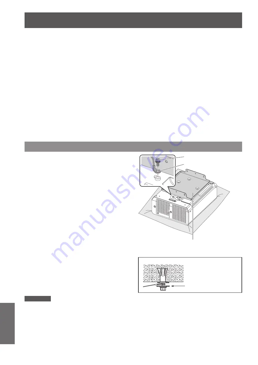
Attachment procedure
Turn the projector upside down and
1 )
place it gently on a soft cloth.
Put the plain washer on the wire rope
2 )
fixing screw.
Put the wire rope through the wire rope
3 )
fixing screw.
Install the wire rope fixing screws to the
4 )
projector and tighten them.
Install the wire ropes to the 2 places in a similar
z
manner.
Wire rope fixing screw: M4 x L12.
Tightening torque of fixing screw: 1.25 ± 0.2 Nm
Attention
Do not use other than the provided Wire rope fixing screw, washer and Safety cable.
z
Install the wire ropes so that they do not sag between the installation portions on the body and those on the ceiling.
z
Ceiling bracket
(Metal fitting attached to the ceiling mount bracket or
projector metal fitting for the ceiling mount bracket)
Wire rope
Wire rope fixing screw
Ceiling mount
Washer
Please also attach the washer
which is additional accessory to
the ceiling mount.


