background image

46

Registration of input signal data

Sub memory

The projector is provided with a sub memory function to register plural pieces of image adjustment data even they
are determined to be the same signal by the frequency and form of the synchronization signal source.
Use this function when the user needs adjustment of picture quality such as aspect switching and white balance
using the same signal source.
Sub-memory contains all data that can be adjusted by signals such as screen aspect ratio and image adjustment
data (BRIGHT, CONTRAST etc.).

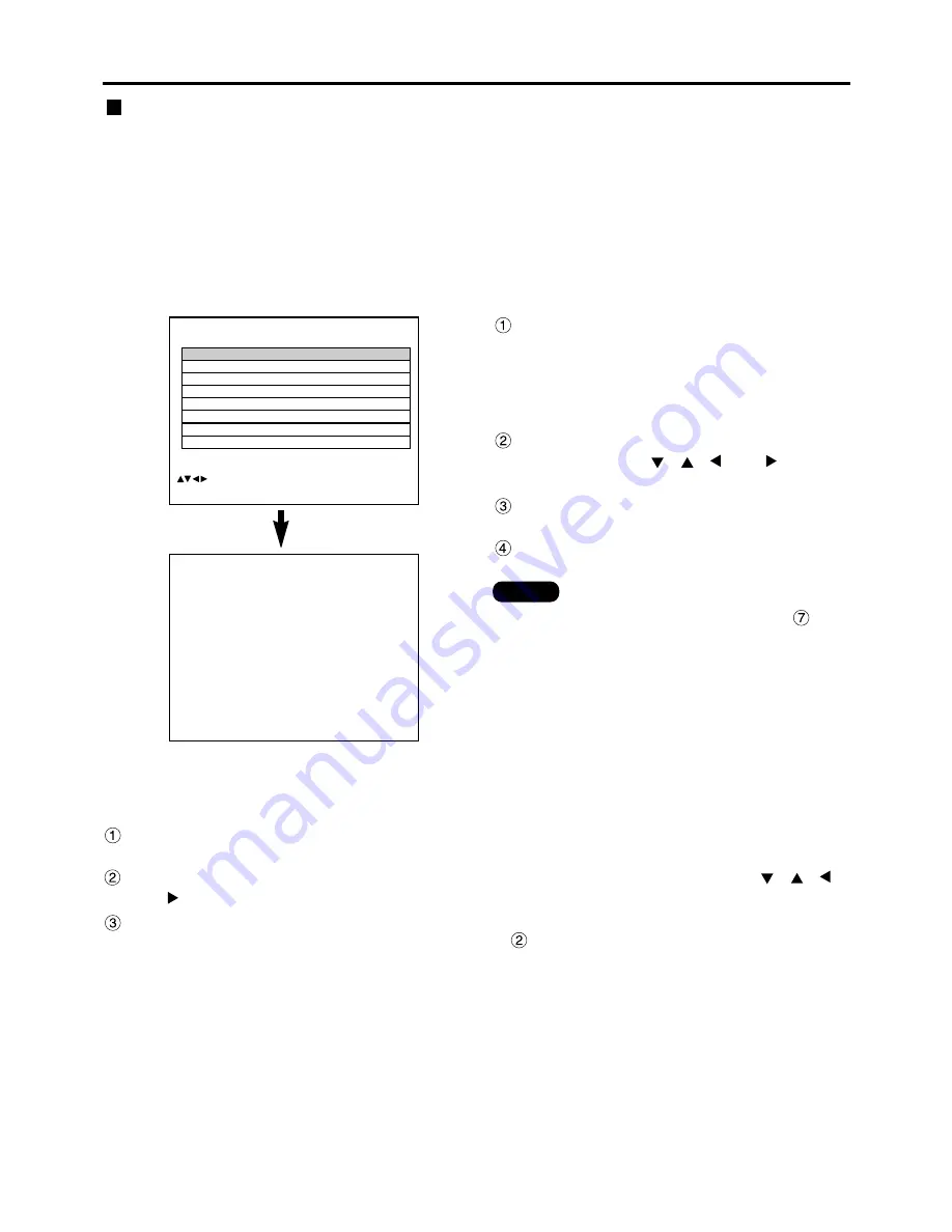
How to register into sub memory

A new signal cannot be registered into sub memory. A new signal must undergo signal registration.

SUB MEMORY LIST

  1- 1:SXGA60-A1
  1- 2:SXGA60-A2
  1- 3:     – – –
  1- 4:     – – –
  1- 5:     – – –
  1- 6:     – – –
  1- 7:     – – –
  1- 8:     – – –

           :SELECT   ENTER:CHANGE   STD:DELETE

REGISTER SUB MEMORY?

  NAME:

SXGA60-A1

  MEMORY NO:

– –

  S.S.NO:

– – –

  INPUT NO:

RGB1

  fH:

  48.00kHz

  fV:

  60.00Hz

  SYNC. STATE:

H(POS)
V(POS)

ENTER:EXECUTE    MENU:ESC

Press the “USER” button on normal
screen (menu is not displayed).

(A “Check sub-memory registration” screen will
appear if sub-memory has not been registered.)
The screen will show a list of the sub-memory
registered for the currently entered signal.

Select the SUB MEMORY number
stored with the 

and 

buttons in the “Signal List”. 
Press the “ENTER” button.

A “Change registered signals” screen will appear.

Press the “ENTER” button.

Procedure to switch to sub memory

Press the “USER” button on normal screen (menu is not displayed).

The screen will show a list of the sub-memory registered for the currently entered signal.

In the “Signal List”, select the sub-memory signal to be switched using the 

and buttons. 
Press the “ENTER” button.

Signal will be switched to the one that was selected in Step 

.

How to erase sub memory

The currently selected SUB MEMORY is deleted by pressing the standard button (STD) at the “REGISTERED SIGNAL
LIST” or the “SUB MEMORY LIST”.

• To rename a registered signal, perform step 

on

page 45.

Note

Summary of Contents for PT-D7700

Page 1: ...is unit TQBJ 0146 1 POWER ON OFF RGB 1 RGB 2 AUX MENU STD LENS OSD 1 4 7 2 5 8 3 6 9 0 NEXT USER LIGHT ID ALL ASPECT ID SET Projector Computer Numetric BRIGHT CONTRAST ON SCREEN SYSTEM SEL FUNC 1 D ZO...

Page 2: ...E PAS OUVRIR ZUR VERMEIDUNG EINES ELEKTRISCHEN SCHLAGES GER T NICHT FFNEN The lightning flash with arrowhead symbol within an equilateral triangle is intended to alert the user to the presence of unin...

Page 3: ...N To assure continued compliance use only shielded interface cables when connecting to computer or peripheral devices Any unauthorized changes or modifications to this equipment could void the user s...

Page 4: ...efault 50 Adjusting the picture 51 Switching the picture mode 51 Adjusting Contrast Bright Color Tint 52 Registering the picture mode settings as presettings 53 DYNAMIC IRIS setting 54 Adjusting the c...

Page 5: ...r modify it in any way High voltages which can cause fire or electric shocks are present inside the projector For any inspection adjustment and repair work please contact an Authorized Service Center...

Page 6: ...ome damaged if struck against hard objects or dropped and injury or malfunctions may result Do not set up the projector in humid or dusty places or in places where the projector may come into contact...

Page 7: ...jects which cannot withstand heat Do not use the old lamp unit The lamp section may break Replacement of the lamp unit should only be carried out after it has completely cooled off otherwise burns may...

Page 8: ...e screen surface Draw window curtains or blinds turn off the lightings near the screen or take other proper measures In rare cases wafture can occur on the screen affected by the warm air from the exh...

Page 9: ...brightness System 3 PC equipped with a DVI D input module an optional item can be attached to the projector for computer image viewing Realization of high resolution picture System 2 The optional high...

Page 10: ...SECURITY password ENTER button page 50 Press this button to enter your menu selection or to run function ON SCREEN button This button turns on and off the on screen indication function Standard STD b...

Page 11: ...ER ON OFF RGB 1 RGB 2 AUX MENU STD LENS OSD 1 4 7 2 5 8 3 6 9 0 NEXT USER LIGHT ID ALL ASPECT ID SET Projector Computer Numetric BRIGHT CONTRAST ON SCREEN SYSTEM SEL FUNC 1 D ZOOM ENTER PAGE UP PAGE D...

Page 12: ...ontrol Power indicator lamp page 39 The lamp lights in red when the MAIN POWER switch is turned to I on It turns to green when the POWER ON button of the remote control or the main unit is pressed LAM...

Page 13: ...o video input S VIDEO button page 39 Switches to S VIDEO input SHUTTER button page 48 Press this button to black out the image temporarily MENU button pages 50 and 88 89 Displays and clears the Main M...

Page 14: ...system they can be connected and controlled with a wired remote control cable M3 jack REMOTE2 terminal page 84 The user can remotely control the main unit by using an external control circuit to this...

Page 15: ...ure 2 The effective control range is approx 7 meters from the beam receiver on the front or rear Do not drop the remote control unit Do not expose remote control unit to any liquid Do not use NiCd bat...

Page 16: ...ion mode selector switch to Projector However if the ID ALL button is pressed the projector can be controlled regardless of the ID number of the projector simultaneous control mode Using the remote co...

Page 17: ...FR EE ZE SH UT TE R A U T O S E T U P S T D L E N S O S D 1 4 7 2 5 8 3 6 9 0 N E X T U S E R LIG HT ID AL L ID SE T P ro je c to r C o m p u te r Nu m et ric BR IG HT C O N T R A S T O N S C R E E N...

Page 18: ...llation geometry When planning the projector and screen geometry refer to the figures below and the information on the next page for reference After the projector is roughly positioned picture size an...

Page 19: ...6 15 35 20 50 25 66 30 81 35 97 41 12 51 43 61 74 23 3 26 8 30 33 5 40 2 50 4 67 3 84 2 101 118 134 10 168 8 202 6 7 09 8 13 9 16 10 19 12 25 15 34 20 50 25 65 30 81 35 96 41 12 51 42 61 73 23 3 26 8...

Page 20: ...22 34 27 95 33 57 39 18 44 80 56 03 67 26 25 4 29 32 9 36 5 43 9 54 10 73 3 91 8 110 1 128 6 146 11 183 9 220 8 4 61 5 28 5 96 6 63 7 97 9 99 13 35 16 71 20 08 23 44 26 80 33 53 40 25 15 1 17 3 19 6...

Page 21: ...26 29 9 33 7 37 4 44 10 56 3 75 1 94 112 11 131 9 150 8 188 5 226 2 4 73 5 42 6 11 6 80 8 18 10 24 13 69 17 14 20 58 24 03 27 48 34 37 41 26 15 6 17 9 20 22 3 26 10 33 7 44 10 56 2 67 6 78 10 90 1 11...

Page 22: ...tance L 0 0446 x Screen diagonal inch 0 1004 ET D75LE2 2 0 3 0 1 4 3 Minimal distance L 0 0412 x Screen diagonal inch 0 0795 Maximal distance L 0 0617 x Screen diagonal inch 0 1064 16 9 Minimal distan...

Page 23: ...3 0 1 16 9 Minimal distance L 0 0460 x Screen diagonal inch 0 0795 Maximal distance L 0 0689 x Screen diagonal inch 0 1064 Minimal distance L 0 0689 x Screen diagonal inch 0 0958 Maximal distance L 0...

Page 24: ...ase a time base corrector TBC must be connected The projector accepts the following signals video S Video analog RGB and digital signals from the PC Some PC models cannot be connected to the projector...

Page 25: ...terminal Blue connected to PB terminal Green connected to Y terminal Video deck TBC built in Example of connecting with VIDEO devices When connecting with a video deck be sure to use the one with a bu...

Page 26: ...R RS 232C G RS 422 R IN RGB 2 IN RGB 2 IN I F PC PC Control PC When the main power of the main unit is turned off also turn off the power of the PC Note Attention For the specifications of the RGB sig...

Page 27: ...W SWS Digital broadcasting tuner DVD player Signal selector Video deck TBC built in Notebook computer Control PC Note When multiple signals of the same type are switched and input to RGB1 IN for examp...

Page 28: ...modules fH 15 kHz 100 kHz fV 24 Hz 120 Hz Dot clock frequency 20 MHz 162 MHz Signals supporting color difference input Types Supported 480i 576i 480p 576p 720 60p 1080 60i 1035 60i 1080 50i 1080 30p 1...

Page 29: ...s Input module Slot Tighten the two screws Remove the slot cover Insert the input module Fix the input module Register the input signal This projector needs to register the type of input signal after...

Page 30: ...ital HD tuner HD serial digital input module ET MD95SD3 DVI input module ET MD75DV SD signal SD signal DVI signal PC Network module ET MD75NT LAN Projector RGB signal input module ET MD95RGB Connectin...

Page 31: ...t support the three value synchronizing input to the H H V and V terminals Do not supply synchronizing input signals to H H V and V terminals when supplying SYNC ON GREEN signals Attention Please purc...

Page 32: ...tween the LINE and Y C input Example Each time AUX button is pressed LINE input Y C input The above cycle is repeated When connecting with a video deck be sure to use the one with built in TBC time ba...

Page 33: ...Module ET MD95VM2 Video signal input module optional ET MD95VM2 Color difference signals Cr Luminance signals Y Video deck TBC built in For details on switching between the video signals connection an...

Page 34: ...nal specifications Upon toggling the input signals are displayed on the screen and cleared automatically SD signal SD signal output active through Serial digital input module optional ET MD95SD1 for 4...

Page 35: ...TOR button Use a 3C2W or superior cable for connection to transmit the image information without error Example 3C2W 3CFB 4CFB 5C2W 5CFB 5CFTX 7CFB etc MAIN IN ET MD95SD2 for 480p 480i 576i 480p Module...

Page 36: ...han listed above or if any unstable signal is connected If this happens switch to a system that is compatible with the signal format using the SYSTEM SELECTOR button Use a 5CFB or superior cable for c...

Page 37: ...ight terminal for TMDS equipped PC The DVI D signal input module supports only a single link Pin No Pin No Signal TMDS data 2 TMDS data 2 TMDS data 2 4 shield T M D S data 4 T M D S data 4 DDC clock D...

Page 38: ...sert the lens and turn it clockwise until it clicks into place Insert the tab on the projection lens cover into the projector and mount the projection lens cover while pressing the lock button How to...

Page 39: ...t projection The temperature monitor TEMP lamp lights up during the warm up period When the warm up is completed the temperature monitor TEMP lamp turns off and the image is projected on the screen If...

Page 40: ...p the light source lamp if the lamp is in the process of cooling down after turning off the power supply To light up the lamp turn on the power supply again when the lamp has been cooled sufficiently...

Page 41: ...ntrol or on the control panel of the main unit Pressing the button changes the setup screen in the order of LENS FOCUS LENS ZOOM and LENS SHIFT Choose an item and adjust it using buttons How to adjust...

Page 42: ...mm diagonal hexagon Vup H left H right Vbottom a b c Fixing screws Lens bracket V up is out of focus V bottom is out of focus The instructions within parentheses apply to ceiling mount installation Tu...

Page 43: ...have been shifted even when the adjustment ended normally In this case manually adjust the CLOCK PHASE If an image with blurred edges or a dark image is supplied a message INCOMPLETE appears indicatin...

Page 44: ...screen will be displayed Select SIGNAL LIST with the and buttons Note MAIN MENU PICTURE POSITION ADVANCED MENU LANGUAGE OPTION TEST PATTERN SIGNAL LIST SECURITY MENU SELECT ENTER SUB MENU REGISTERED S...

Page 45: ...H 48 08kHz fV 72 17Hz SYNC STATE H POS V POS ENTER EXECUTE MENU ESC RENAME NAME SVGA72 A2 MEMORY NO A2 S S NO INPUT NO RGB1 fH 48 08kHz fV 72 17Hz SYNC STATE H POS V POS NEXT FIGURE FONT SELECT ENTER...

Page 46: ...Hz fV 60 00Hz SYNC STATE H POS V POS ENTER EXECUTE MENU ESC Press the USER button on normal screen menu is not displayed A Check sub memory registration screen will appear if sub memory has not been r...

Page 47: ...1 A2 H7 and H8 signals are registered displays the sub memory number Details of registered signal Restrictions The maximum sub memory items that can be registered for the projector are 96 including th...

Page 48: ...during the presentation Press the D ZOOM button of the remote control The image is zoomed in Change the magnification with the D ZOOM button The magnification can be adjusted from 1 0 to 3 0 times Us...

Page 49: ...RGB1 A6 SVGA72 A6 RGB1 A7 SVGA72 A7 RGB1 A8 SVGA72 A8 RGB1 SELECT ENTER DETAILS STD DELETE OPTION PROJECTOR ID 2 SETTING FRONT F LAMP SELECT DUAL LAMP POWER HIGH RS232C SETTING OSD POSITION 2 SYSTEM...

Page 50: ...MENU SELECT ADJUST CONTRAST 32 Returning to the previous screen When the MENU is on the screen pressing the MENU button returns to the previous page When the MAIN MENU is on the screen pressing the ME...

Page 51: ...displayed Select PICTURE MODE with the buttons Switch PICTURE MODE with the buttons DYNAMIC The picture becomes suitable for the use in well lighted areas GRAPHIC The picture becomes suitable for inpu...

Page 52: ...be displayed for CONTRAST and BRIGHT by the remote control Refer to the following table To register the picture mode settings which have been adjusted and use them as the presettings follow the proced...

Page 53: ...ngs as presettings The screen settings which have been adjusted by following the adjustment procedure on the previous page can be registered Press the MENU button The MAIN MENU screen will be displaye...

Page 54: ...USER in step Press the ENTER button The DYNAMIC IRIS screen will be displayed Select AUTO IRIS MANUAL IRIS or DYNAMIC GAMMA with the buttons Adjust the compensation amount with the buttons The contras...

Page 55: ...tment is not successful press STD standard button when the individual adjustment screen is displayed to restore the factory default setting only for the displayed item The color temperature cannot be...

Page 56: ...ion Sharpens the outline of the image Switches the gamma modes Operation Four types OFF no correction 1 low 2 middle 3 high factory default 2 Noise reduction Switches the noise reduction effect mode N...

Page 57: ...ith the buttons MAIN MENU PICTURE POSITION ADVANCED MENU LANGUAGE OPTION TEST PATTERN SIGNAL LIST SECURITY MENU SELECT ENTER SUB MENU Press the ENTER button The POSITION screen will be displayed Selec...

Page 58: ...SUB MENU ZOOM INTERLOCKED OFF V 100 H 100 HV 100 MENU SELECT CHANGE Press the ENTER button The SIZE adjustment screen will be displayed Select the desired item with the buttons Adjust with the button...

Page 59: ...into the panels aspect ratio 4 3 for PT D7700U and 16 9 for PT DW7000U VID AUTO The projector identifies the video ID VID embedded in the picture signals and displays the picture by automatically swi...

Page 60: ...the ENTER button The KEYSTONE screen will be displayed Adjust the KEYSTONE horizontally with the buttons The value changes from 0 to 127 Adjust the vertical LINEARITY with the buttons The value chang...

Page 61: ...y default Note In DIGITAL CINEMA REALITY mode the image quality will be deteriorated if 30p FIXED or 25p FIXED is selected when the signal is not a 2 2 pulldown signal Note ADVANCED MENU DIGITAL CINEM...

Page 62: ...elect the desired item for adjustment with the buttons Adjust blanking with the buttons The value changes from 0 to 511 Press button to move the blanking zone upward button to downward Press button to...

Page 63: ...nal If vertical stripes appear on the screen or the image is partly missing increase or decrease the displayed value while observing the screen to achieve the optimal value Adjusting the input resolut...

Page 64: ...n green The optimal value is the point where the green area becomes dark and clear Adjusting the clamp position Use the clamp position adjustment to achieve the optimal value when dark areas of the im...

Page 65: ...ese lines overlap Red line Red line Green line Green line Adjustment marker When the MARKER is set to ON the image position adjustment marker is displayed The optimal point is the position where the r...

Page 66: ...yed Select the BRIGHT INSIDE with the buttons Adjust the compensation value 0 255 with the buttons Select the part of Upper Lower Right Left with buttons With the buttons adjust the width 0 to 255 whe...

Page 67: ...ease make readjustment accordingly Note ADVANCED MENU DIGITAL CINEMA REALITY AUTO FORMAT SMPTE BLANKING INPUT RESOLUTION CLAMP POSITION EDGE BLENDING OFF SYNC TERM 75 RASTER POSITION RASTER POSITION V...

Page 68: ...a light green Menus setting items adjustment screens and control button names will be displayed in the language the user chooses The available languages are English German DEUTSCH French FRAN AIS Spa...

Page 69: ...RGB ET MD95VM2 For the setting of AUTO2 For the setting of ET MD95VM2 YCbCr ET MD95VM2 For the setting of AUTO1 S video Video terminal input signal AUTO1 NTSC PAL SECAM PAL60 NTSC4 43 AUTO2 NTSC PAL M...

Page 70: ...60 1080 24p 27 00 24 1080 50i 28 12 50 1080 30p 33 75 30 1080 25p 28 12 25 1080 24sF 27 00 48 Others RGB mode only 576p 31 25 50 Supported Factory default Supported To use the signal in the mode with...

Page 71: ...o 64 If the projectors are given ID numbers their remote controls must be assigned the same ID numbers respectively If the ID number of a projector is set to ALL it can be controlled by the remote con...

Page 72: ...MENU LANGUAGE OPTION TEST PATTERN SIGNAL LIST SECURITY MENU SELECT ENTER SUB MENU Press the MENU button The MAIN MENU screen will be displayed Select OPTION with the buttons Press the ENTER button Th...

Page 73: ...sumption reduce operating noise and extend lamp service life LOW is set automatically when Long Life Lamp Units are used If any of SINGLE LAMP 1 and LAMP 2 has been selected when a currently lit lamp...

Page 74: ...IGNAL 1 64 ENTER NEXT Press the MENU button The MAIN MENU screen will be displayed Press and buttons to select OPTION Press the ENTER button The OPTION screen will be displayed Press and buttons to se...

Page 75: ...th the buttons These values can be adjusted from 0 to 2 048 3COLORS R R 2048 G 0 B 0 MENU SELECT ADJUST Adjustment The effects of correcting the adjustment color When tuning the correction color that...

Page 76: ...ION with the buttons Press the ENTER button The OPTION screen will be displayed Select COLOR MATCHING with the buttons Select MEASURE with the buttons Press the ENTER button The MEASURE MODE screen wi...

Page 77: ...message PROGRESS appears during automatic adjustment When the adjustment is complete the system returns to the input screen MODE DEFAULT WIDE Applicable resolution 640 x 400 640 x 480 800 x 600 832 x...

Page 78: ...played Select OUTPUT RESOLUTION with the buttons Auto signal When unregistered signals are to be input frequently because the unit is used at conferences or other venues the screen display position ca...

Page 79: ...e user can select the window that is displayed by priority when two windows overlap MAIN WINDOW The main window is displayed by priority SUBWINDOW The subwindow is displayed by priority Linearity The...

Page 80: ...75NT LINE input RGB input VIDEO input S VIDEO input VIDEO input S VIDEO input RGB input Y C input YCbCr input RGB input RGBrealiry input YCbCr input YPbPr input LINE input Y C input YCbCr input YCbCr...

Page 81: ...ching operation If LINE or Y C is selected use buttons to choose AUX LINE or AUX Y C and then use the buttons to switch to AUTO1 or AUTO2 The selected signaling system appears The picture may be disto...

Page 82: ...nchronization 9 600bps None 8 bits 1 bit None None PC D Sub 9 pin male Communication cable D Sub 9 pin male D Sub 9 pin female Communication cable Terminal section on Projector 1 Terminal section on P...

Page 83: ...are invalid While the lamp is ON and being controlled a PON command will not be accepted Parameter VID VIDEO SVD S VIDEO RG1 RGB1 RG2 RGB2 AUX AUX Parameter 0 DUAL 1 SINGLE 2 LAMP 1 3 LAMP 2 Paramete...

Page 84: ...a different room STANDBY ON LAMP Remote terminal External control Remote terminal External control RGB1 VIDEO RGB2 S VIDEO Using the REMOTE 2 terminal Names of terminals GND POWER RGB1 RGB2 VIDEO S VI...

Page 85: ...th the buttons Search through the various types of test patterns with the buttons Cycle of displayed internal test patterns MENU screen All white MENU screen All black MENU screen Flag MENU screen Fla...

Page 86: ...RITY with the buttons Select PASSWORD with the buttons Switch PASSWORD with the buttons ON Password entry is enabled OFF Password entry is disabled Press the ENTER button The PASSWORD screen will be d...

Page 87: ...e changed Setting the text The set text can be permanently displayed below the pictures being projected Changing the text The characters displayed in the text can be changed when ON has been selected...

Page 88: ...ting section of the main unit Setting the on screen indication function Procedure of setting Hold down the MENU button for 3 or so seconds If the on screen function is OFF the on screen indication wil...

Page 89: ...F the on screen indication will now appear and the CP OPTION item will be added to the main menu Select SYSTEM SELECTOR with the buttons Press the ENTER button The SYSTEM SELECTOR screen will be displ...

Page 90: ...hat E mail feature is available in your system Use a LAN cable of straight connection and compatible to Category 5 The length of LAN cable must be 100 m or shorter Name and function of network module...

Page 91: ...NU SELECT ENTER SUB MENU OPTION PROJECTOR ID 2 SETTING FRONT F LAMP SELECT DUAL LAMP POWER HIGH RS232C SETTING OSD POSITION 2 SYSTEM INFORMATION COLOR MATCHING 3COLORS VIDEO SETTING NETWORK SETTING ME...

Page 92: ...used Displays the MAC address Media Access Control Address which is proper to the network device This function may be needed when to use the DHCP server Display of host name and setting DHCP client f...

Page 93: ...utton Click this item and an E mail setting page appears Link button to time setting If time setting goes wrong immediately after setting time the battery must be replaced Link button to network setti...

Page 94: ...if DHCP server is not used Enter the projector name Enter this field when the host name is required such as when to use the DHCP server Advanced control page On screen status is displayed even if the...

Page 95: ...mail server SMTP The user can enter the location of for example the installed projector so that the recipient may easily identify the originator of the E mail maximum 63 characters Enter the E mail a...

Page 96: ...ature inside the projector has reached the value set in the above field Warning output air Temperature exhaust temperature has reached the value set in the above field Select the conditions for sendin...

Page 97: ...he operation is complete Do not use a pencil or other fragile thing to depress the function switch Note Image file control page Folder selection button This button specifies the folder to store the im...

Page 98: ...Remove the object that is blocking the ventilation port Move the projector to a temperature of 0 to 40 C and the humidity of 20 to 80 no condensation Turn off the MAIN POWER switch using the procedure...

Page 99: ...careful not to suck in the air filter itself The air filter must be fitted in place when using the projector Using the projector without the air filter fitted inside dirt and dust are sucked into the...

Page 100: ...vidual lamps and working conditions lamps may reduce their life affected by the times of lighting and the intervals between previous lighting and next lighting Therefore it is strongly recommended for...

Page 101: ...l the screws turn freely Then hold the handle of the lamp unit and gently pull it out from the projector Caution The lamp unit will be hot after it has been used You might get burned if you touch it w...

Page 102: ...the OPTION screen and select SYSTEM INFORMATION with the and buttons 12 Press the ENTER button The SYSTEM INFORMATION screen will be displayed 15 Press the ENTER button When OK is displayed press the...

Page 103: ...gth and color tint correctly adjusted Refer to page 52 Is the device s connected to the projector adjusted correctly Pale color bad color tint Are dry batteries consumed Is polarity correct in battery...

Page 104: ...z 576i horizontally 15 63 kHz vertically 50 Hz 576p horizontally 31 25 kHz vertically 50 Hz 720 60p horizontally 45 kHz vertically 60 Hz 1035 60i horizontally 33 75 kHz vertically 60 Hz 1080 60i horiz...

Page 105: ...4 Mass 22 k 48 lb without lens Working environment condition 1 Ambient temperature 0 to 40 C 0 to 35 C when setting for lamp power is HIGH and lamp select is DUAL Ambient humidity 10 to 80 no condensa...

Page 106: ...88 9 60 0 72 0 75 0 60 0 74 6 75 0 60 0 60 0 59 9 50 0 59 9 50 0 Applicable input signal data Display mode VGA400 VGA480 XGA MXGA SVGA SXGA SXGA UXGA MAC16 MAC21 1080 60i 720 60p 480i 576i 480p 576p...

Page 107: ...red trademark of the Microsoft Corporation U S A in the U S and other countries Netscape and Netscape Navigator are registered trademarks of the Netscape Communications Corporation in the U S and othe...

Page 108: ...exclamation dans un triangle avertit l usager de la pr sence d instructions importantes concernant l utilisation et l entretien r paration dans la litt rature accompagnant le produit ATTENTION Cet ap...

Page 109: ...es puissent tre faites Ne pas couvrir le filtre et la sortie d air Cela risque de faire surchauffer le projecteur et causer un incendie ou endommager le projecteur Ne pas surcharger la prise de couran...

Page 110: ...des r cipients de liquide sur le projecteur Si de l eau se renverse sur le projecteur s adresser un centre technique agr Si n importe quel liqui de s infiltre l int rieur du projecteur entrer en cont...

Page 111: ...sions aux yeux Ne pas placer les mains ou autres objets pr s de la sortie d air De l air chaud sort par l ouverture de sortie d air Ne pas placer les mains ou le visage ou d autres objets qui ne peuve...

Page 112: ...n fort contraste et d image nettes si la lumi re ext rieure ou l clairage interf re avec la surface de l cran Tirez les rideaux des fen tres ou les stores teignez l clairage pr s de l cran ou prenez d...

Page 113: ...allume pas 1 500 heures 1 selon les caract ristiques des lampes individuelles et les conditions de travail la vie de service des lampes peut tre r duite par le nombre d allumages et les intervalles e...

Page 114: ...s pour desserrer chacune des deux vis de fixation de la lampe jusqu ce qu elles tournent facilement Ensuite saisissez la poign e de la lampe et tirez doucement pour la sortir du projecteur Attention L...

Page 115: ...rz sur la touche ENTER Les heures d utilisation de la lampe sp cifi e seront remises z ro Si plus d une lampe a t remplac e r p tez la proc dure partir de l tape 14 13 Maintenez presse la touche ENTER...

Page 116: ...e Panasonic Way 4E 7 Secaucus NJ 07094 201 392 4443 3330 Cahuenga Blvd West Los Angels CA 90068 323 436 3500 Technical Support 800 524 1448 800 526 6610 FAX 201 392 6514 E Mail pbtssupport panasonic c...

Reviews: