Panasonic PT-D10000E Service Manual Download Page 21

7 Using a Wired Remote Control

7.1. Connection Example

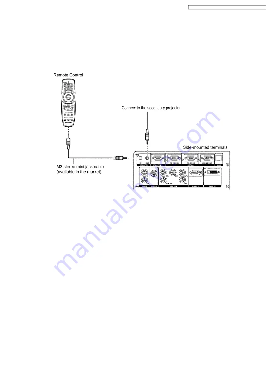
When multiple main units are connected as part of the system, connect to units with a M3 stereo mini jack cable (sold separately)
to simultaneously control multiple main units with a single remote control through the REMOTE1 IN/OUT terminal. It is effective to
use the wired remote control in the environment in which an obstacle stands in the light path or where devices are susceptible to
outside light.


·


Use a two-wire shielded cable with a length of 15 m or less. If the length of the cable exceeds 15 m, the shielding of the cable
may not be sufficient and the remote control may not work.

7.2. Setting Projector ID Number to Remote Control

Every projector has its ID number and the ID number of the controlling projector must be set to the remote control in advance so
that the user can operate the remote control. The ID number of the projector is set to “ALL” on shipping, and use the ID ALL button
of the remote control when using only a single projector.

Procedure of ID setting

Press ID SET, and then within 5 seconds, press the two numeric (0-9) buttons which correspond to the ID number that has been
set for the projector.


·


The main unit has its ID number (1-64 or ALL), and set to remote control when the ID number is 1-9 as 01-09. When the
ID number is "ALL", set it with the ID ALL button of the remote control unit.


·


Do not press the ID SET button accidentally or carelessly because the ID number on the Remote Control can be set even
when no projector is around.


·


If you do not enter the two-digit ID number within 5 seconds after the ID SET button has been pressed, the ID number will
remain at the number that was set before the ID SET button was pressed.


·


Your specified ID number is stored in the remote control unit unless another one is specified later. However, the stored ID
will be erased if the batteries of the remote control are left exhausted. When the batteries are replaced, set the same ID
number again.

21

PT-D10000U / PT-D10000E / PT-DW10000U / PT-DW10000E

Summary of Contents for PT-D10000E

Page 1: ...atsushita Electric Industrial Co Ltd All rights reserved Unauthorized copying and distribution is a violation of law PT D10000U PT D10000E PT DW10000U PT DW10000E DLP Based Projector ORDER NO VED0612375C0 D10 ...

Page 2: ...2 PT D10000U PT D10000E PT DW10000U PT DW10000E ...

Page 3: ...odule 33 12 11 Removal of R P C Board 33 12 12 Removal of R2 P C Board 34 12 13 Removal of R3 P C Board 35 12 14 Removal of S P C Board 35 12 15 Removal of SL P C Board 36 12 16 Removal of K Module 36 12 17 Removal of B Q Module 36 12 18 Removal of PF Modele 39 12 19 Removal of PC Module 39 12 20 Removal of Projection Lens 41 12 21 Removal of Lamp Unit 41 12 22 Removal of Iris Unit 42 12 23 Remova...

Page 4: ... 107 17 2 A P C Board Component Side 108 17 3 G P C Board Foil Side 109 17 4 G P C Board Component Side 110 17 5 S P C Board 111 18 Terminal guide of ICs and transistors 113 19 Exploded Views 114 20 Replacement Parts List 120 4 PT D10000U PT D10000E PT DW10000U PT DW10000E ...

Page 5: ... 1 Prepare the measuring circuit as shown in Fig 1 Be sure to use a voltmeter having the performance described in Table 1 Fig 1 Table 1 Fig 2 2 Assemble the circuit as shown in Fig 2 Plug the power cord in a power outlet 3 Connect M1 to T1 according to Fig 2 and measure the voltage 4 Change the connection of M1 from T1 to T2 and measure the voltage again 5 The voltmeter must read 0 375 V or lower ...

Page 6: ...2 Specifications PT D10000U PT D10000E PT DW10000U PT DW10000E 6 ...

Page 7: ...PT D10000U PT D10000E PT DW10000U PT DW10000E 7 ...

Page 8: ...The reset the bimetal action press the protrusion of the bimetal unit you feel a click 3 2 Interlock Switch To ensure safety this projector is designed so that the power cannot be turned on when the lamp unit cover is opened or installed incorrectly If opening the lamp unit cover during operation the projector will be switched to standby mode fans stop and lamps turn off 4 Serviceman Mode This pro...

Page 9: ...splayed 3 Select PASSWORD using the or buttons and press the ENTER button The PASSWORD screen will be displayed 4 Input the password 1565 with the numeric buttons 0 to 9 of the remote control unit and press the ENTER button Note Asterisk will appear for the password numbers 5 Press the MENU button then SERVICEMAN MODE menu will be displayed 9 PT D10000U PT D10000E PT DW10000U PT DW10000E ...

Page 10: ...n The PASSWORD screen will be displayed 4 Input the password 0000 with the numeric buttons 0 to 9 of the remote control unit and press the ENTER button Note Asterisk will appear for the password numbers 5 Press the MENU button then USER MODE menu will be displayed 4 3 Functions in Serviceman Mode 4 3 1 Additional Functions for ADVANCED MENU FRAME LOCK Sets the frame lock V MASK Sets the V mask PLL...

Page 11: ...R CLEANING ON Default setting OFF Disables automatic cleaning operation SYSTEM INFORMATION The number of pages of screens displayed when selecting becomes 4 in Serviceman Mode from 2 in User Mode SELF CHECK Page 1 and page 2 are the same as User Mode the display of DDP formatter software version is added on page 3 and the display of SELF CHECK result is added to page 4 11 PT D10000U PT D10000E PT ...

Page 12: ...TPUT Adjusts brightness with Dynamic Iris It darkens as the value becomes small CUT OFF Sets whether to display each color of Red Green and Blue ENTRY SIGNAL CLEAR Deletes all entry signals REMOTE 2 MODE Sets the function of REMOTE2 terminal 12 PT D10000U PT D10000E PT DW10000U PT DW10000E ...

Page 13: ...pin 2 Be able to allocate SHUTTER into the pin 8 POWER ON SHUTTER OPEN Opens the shutter when power ON CLOSE Closes the shutter when power ON POWER OFF SHUTTER OPEN Opens the shutter when power OFF CLOSE Closes the shutter when power OFF IGNORE Does not control the shutter when power OFF 13 PT D10000U PT D10000E PT DW10000U PT DW10000E ...

Page 14: ...iagnosis display check the part of the cause according to the content of the error code table below 5 1 Error code Table Error code Contents Shutdown Error display condition Remarks U11 Temperature warning IN Intake air temperature is the specific value or higher U12 Temperature warning OPT Optical module temperature is the specific value or higher U13 Temperature warning OUT Lamp surroundings tem...

Page 15: ... 1 2006 FE1 Fan error 1 P UNIT FAN The fan stops for 5 seconds or longer Power unit fan FE2 Fan error 2 LAMP1 FAN Lamp fan 1 FE3 Fan error 3 LAMP2 FAN Lamp fan 2 FE4 Fan error 4 LAMP3 FAN Lamp fan 3 FE5 Fan error 5 LAMP4 FAN Lamp fan 4 FE6 Fan error 6 BALLAST1 FAN Ballast fan 1 FE7 Fan error 7 BALLAST3 FAN Ballast fan 3 FE8 Fan error 8 RADIATOR FAN Radiator fan FE9 Fan error 9 EXAUST FAN C Exhaust...

Page 16: ...6 Lens shift error The circuit for lens position detection is abnormal Explanatory notes of shutdown column Shutdown occurs Shutdown does not occur 1 Shutdown occurs only when starting Shutdown does not occur even if the temperature becomes less than 5 C during normal operating 2 Shutdown occurs when all lamps cannot be lit 16 PT D10000U PT D10000E PT DW10000U PT DW10000E ...

Page 17: ...erminals located in its terminal section on the side and this terminal is compliant with RS 232C RS 422 Also a serial output terminal is provided to enable plural projector control 6 1 Example of Connection RS 232C RS 422 17 PT D10000U PT D10000E PT DW10000U PT DW10000E ...

Page 18: ... 422 6 3 Communication Conditions Factory Setting 6 4 Procedure of Communication Condition Settings 1 Press the MENU button The MAIN MENU screen will be displayed 2 Select OPTION2 using the or buttons 18 PT D10000U PT D10000E PT DW10000U PT DW10000E ...

Page 19: ...s 7 Press buttons to switch SERIAL IN RS 232C and RS 422 will switch each time the button is pressed 8 Select communication conditions using the or buttons 9 Press buttons to confirm the setting 10 Press the MENU button 3 times The on screen indications disappear and the system returns to the normal screen 6 5 Control commands 6 6 Cable specifications 19 PT D10000U PT D10000E PT DW10000U PT DW1000...

Page 20: ...Note To connect the computer to the SERIAL terminal prepare an adequate communication cable that fits to your personal computer 20 PT D10000U PT D10000E PT DW10000U PT DW10000E ...

Page 21: ...t to ALL on shipping and use the ID ALL button of the remote control when using only a single projector Procedure of ID setting Press ID SET and then within 5 seconds press the two numeric 0 9 buttons which correspond to the ID number that has been set for the projector The main unit has its ID number 1 64 or ALL and set to remote control when the ID number is 1 9 as 01 09 When the ID number is AL...

Page 22: ...sult your dealer or Authorized Service Center for the adjustment software 8 3 Replacement of the lithium battery on the A P C Board If the lithium battery will be empty replace it with a new one CR2032 or equivalent Cautions Explosion may occur if replacing the battery with an incorrect one Dispose of used batteries according to the instructions 9 Cautions for Service 9 1 Servicing Methods Never u...

Page 23: ...10 Parts Location 10 1 Electrical Parts Location 10 2 Electromechanical Parts Location 23 PT D10000U PT D10000E PT DW10000U PT DW10000E ...

Page 24: ...t the dealer Replacement lamp unit model No ET LAD10000 single bulb ET LAD1000F 4 bulbs Rating 250 W Other lamps than specified above cannot be used Be sure to use the specified lamp 11 2 Timing of Lamp Unit Replacement The lamp used for the light source has its due life The life of light source lamp used in the main unit is 2 000 hours However it may happen that the lamp becomes dead will not lig...

Page 25: ...11 3 Indication of Lamp Monitor 25 PT D10000U PT D10000E PT DW10000U PT DW10000E ...

Page 26: ...12 Disassembly Instructions 12 1 Flowchart for Disassembly To assemble reverse the disassembly procedures 26 PT D10000U PT D10000E PT DW10000U PT DW10000E ...

Page 27: ...cover lock buttons pull the cover forward to remove it 2 Unscrew the 2 screws and remove the front case 3 Loosen the 1 screw until it idles and open the lamp unit cover 4 Unscrew the 5 screws and remove the upper case 27 PT D10000U PT D10000E PT DW10000U PT DW10000E ...

Page 28: ...and remove the FH Module Note The FH Module is connected onto the A P C Board with the connector Work carefully when removing it 3 Unscrew the 6 screws and remove the A P C Board 12 4 Removal of CL P C Board 1 Loosen the 1 screw until it idles and take the filter cleaning unit out 28 PT D10000U PT D10000E PT DW10000U PT DW10000E ...

Page 29: ...2 2 Removal of Upper Case 2 Unscrew the 4 screws and remove the FH Module 12 6 Removal of G P C Board 1 Remove the upper case according to the section 12 2 Removal of Upper Case 2 Unscrew the 2 screws and remove the blindfold board 3 Unscrew the 6 screws and remove the connection terminals panel with S P C Board and SL P C Board 29 PT D10000U PT D10000E PT DW10000U PT DW10000E ...

Page 30: ...e the signal processing block 5 While pressing to shut each hook of the 3 resinous stands remove the NN Module 6 Unscrew the 19 screws and remove the connection terminals metal fittings 30 PT D10000U PT D10000E PT DW10000U PT DW10000E ...

Page 31: ...g it 12 7 Removal of J P C Board 1 Remove the A P C Board according to the section 12 3 Removal of A P C Board 2 Unscrew the 4 screws and remove the J metal fittings 3 Unscrew the 2 screws and remove the J P C Board 12 8 Removal of J2 J3 P C Board The procedure is described as an example of J2 P C Board 31 PT D10000U PT D10000E PT DW10000U PT DW10000E ...

Page 32: ...and remove the J2 P C Board 12 9 Removal of L1 L2 L3 L4 P C Board The procedure is described as an example of L2 P C Board 1 Loosen the 1 screw until it idles and open the lamp unit cover 2 Loosen the 3 screws until they idle and remove the lamp unit 2 32 PT D10000U PT D10000E PT DW10000U PT DW10000E ...

Page 33: ... according to the section 12 2 Removal of Upper Case 2 While pressing to shut each hook of the 3 resinous stands remove the NN Module 12 11 Removal of R P C Board 1 While pressing the projection lens cover lock buttons pull the cover forward to remove it 33 PT D10000U PT D10000E PT DW10000U PT DW10000E ...

Page 34: ...ase 3 Unscrew the 2 screws and remove the R P C Board 12 12 Removal of R2 P C Board 1 Loosen the 1 screw until it idles and open the lamp unit cover 2 Unscrew the 2 screws and remove the R2 P C Board 34 PT D10000U PT D10000E PT DW10000U PT DW10000E ...

Page 35: ... 2 screws and remove the R3 P C Board 12 14 Removal of S P C Board 1 Remove the upper case according to the section 12 2 Removal of Upper Case 2 Unscrew the 2 screws and remove the blindfold board 3 Unscrew the 6 screws and remove the connection terminals panel 35 PT D10000U PT D10000E PT DW10000U PT DW10000E ...

Page 36: ...crew the 2 screws and remove the SL P C Board 12 16 Removal of K Module 1 Remove the signal processing block according to the steps 1 through 4 in the section 12 6 Removal of G P C Board 2 Unscrew the 5 screws and remove the K Module 12 17 Removal of B Q Module The procedure is described as an example of Ballast 1 36 PT D10000U PT D10000E PT DW10000U PT DW10000E ...

Page 37: ...oosen each of 3 screws until they idle remove the lamp units 1 and 2 3 Unscrew each of 1 screw and release each of 1 lamp unit terminal of Ballast 1 and Ballast 2 4 Unscrew the 6 screws and remove the block of Ballast 1 and Ballast 2 37 PT D10000U PT D10000E PT DW10000U PT DW10000E ...

Page 38: ...llast fan mesh 6 Unscrew the 3 screws and separate the Ballast 1 and Ballast 2 7 Unscrew the 2 screws and remove the ballast fan 8 Unscrew the 3 screws and separate the ballast PFC cases 1 and 2 38 PT D10000U PT D10000E PT DW10000U PT DW10000E ...

Page 39: ... to the steps 1 through 8 in the section 12 17 Removal of B Q Module 2 Unscrew the 4 screws and remove the PF Module 12 19 Removal of PC Module 1 Remove the upper case according to the section 12 2 Removal of Upper Case 2 Unscrew the 4 screws and remove the DMD duct block 39 PT D10000U PT D10000E PT DW10000U PT DW10000E ...

Page 40: ... 3 Unscrew the 3 screws and remove the PC block 4 Unscrew the 4 screws and remove the PC case cover 5 Unscrew the 4 screws and remove the PC Module 40 PT D10000U PT D10000E PT DW10000U PT DW10000E ...

Page 41: ...ove it 2 While holding down the projection lens lock button turn the projection lens counterclockwise and then pull it off 12 21 Removal of Lamp Unit The procedure is described as an example of lamp unit 2 1 Loosen the 1 screw until it idles and open the lamp unit cover 41 PT D10000U PT D10000E PT DW10000U PT DW10000E ...

Page 42: ...amp unit arrow positions shown in right figure and confirm the lamp unit is inserted securely Then tighten the 3 screws fixing the lamp unit and close the lamp unit cover 12 22 Removal of Iris Unit 1 Remove the upper case according to the section 12 2 Removal of Upper Case 2 Unscrew the 2 screws and remove the dynamic iris cover 42 PT D10000U PT D10000E PT DW10000U PT DW10000E ...

Page 43: ... to the section 12 2 Removal of Upper Case 2 Unscrew the 4 screws and remove the rear metal fittings 3 Unscrew the 2 screws and remove the shading board 4 Disconnect wiring connection to the 2 bimetals 5 Loosen each of 3 screws until they idle remove the 4 lamp units 43 PT D10000U PT D10000E PT DW10000U PT DW10000E ...

Page 44: ... screw and release 4 lamp unit terminals in total of the 4 ballasts 7 Unscrew the 2 screws and remove the dynamic iris cover 8 Unscrew the 3 screws and remove the iris unit 44 PT D10000U PT D10000E PT DW10000U PT DW10000E ...

Page 45: ...color prism block and analysis block 10 Unscrew each of 2 screws and remove the 4 lamp duct blocks 11 Unscrew the 4 screws and separate the analysis block and color prism block with lamp case 45 PT D10000U PT D10000E PT DW10000U PT DW10000E ...

Page 46: ...move the 4 lamp cases 3 Unscrew the 2 screws and remove the optical holding metal fixture 4 Unscrew each of 2 screws and remove the 2 bimetals 5 Unscrew the 2 screws and remove the color prism fan 12 25 Removal of DMD Block and Liquid Cooling Unit Note Before attempting the removing shift the lens to the foremost position 46 PT D10000U PT D10000E PT DW10000U PT DW10000E ...

Page 47: ...emoval of Upper Case 3 Unscrew the 4 screws and remove the DMD duct block 4 Unscrew the 3 screws and release the block of liquid cooling unit radiator and reserve tank 5 Unscrew the 2 screws and remove the mechanical shutter 6 Unscrew the 3 screws and remove the DMD block and liquid cooling unit 47 PT D10000U PT D10000E PT DW10000U PT DW10000E ...

Page 48: ... 3 screws and remove the engine base 12 27 Removal of Lens Mount Unit Note Before attempting the removing shift the lens to the foremost position 1 Remove the projection lens DMD block liquid cooling unit and analysis mirror according to the section 12 26 Removal of Analysis Mirror 2 Remove the color prism block and analysis block according to the steps 2 through 9 in the section 12 23 Removal of ...

Page 49: ...13 Troubleshooting The alphabets A PC etc in the left box of the inspection items indicate the names of P C Boards or modules to be checked 49 PT D10000U PT D10000E PT DW10000U PT DW10000E ...

Page 50: ...50 PT D10000U PT D10000E PT DW10000U PT DW10000E ...

Page 51: ...51 PT D10000U PT D10000E PT DW10000U PT DW10000E ...

Page 52: ...52 PT D10000U PT D10000E PT DW10000U PT DW10000E ...

Page 53: ...53 PT D10000U PT D10000E PT DW10000U PT DW10000E ...

Page 54: ...54 PT D10000U PT D10000E PT DW10000U PT DW10000E ...

Page 55: ...55 PT D10000U PT D10000E PT DW10000U PT DW10000E ...

Page 56: ...56 PT D10000U PT D10000E PT DW10000U PT DW10000E ...

Page 57: ...57 PT D10000U PT D10000E PT DW10000U PT DW10000E ...

Page 58: ...58 PT D10000U PT D10000E PT DW10000U PT DW10000E ...

Page 59: ...59 PT D10000U PT D10000E PT DW10000U PT DW10000E ...

Page 60: ...60 PT D10000U PT D10000E PT DW10000U PT DW10000E ...

Page 61: ...61 PT D10000U PT D10000E PT DW10000U PT DW10000E ...

Page 62: ...62 PT D10000U PT D10000E PT DW10000U PT DW10000E ...

Page 63: ...63 PT D10000U PT D10000E PT DW10000U PT DW10000E ...

Page 64: ...64 PT D10000U PT D10000E PT DW10000U PT DW10000E ...

Page 65: ...65 PT D10000U PT D10000E PT DW10000U PT DW10000E ...

Page 66: ...66 PT D10000U PT D10000E PT DW10000U PT DW10000E ...

Page 67: ...67 PT D10000U PT D10000E PT DW10000U PT DW10000E ...

Page 68: ...68 PT D10000U PT D10000E PT DW10000U PT DW10000E ...

Page 69: ...ction Block Diagram 1 4 Interconnection Block Diagram 1 4 G P C Board LH P C Board SL P C Board R3 P C Board R2 P C Board LV P C Board R P C Board S P C Board CL P C Board PC Module K Module NN Module PT D10000U PT D10000E PT DW10000U PT DW10000E 69 ...

Page 70: ...rconnection Block Diagram 2 4 G P C Board L2 P C Board E P C Board L1 P C Board E P C Board J3 P C Board J2 P C Board B Module PF Module PF Module Q Module B Q Module B Module Q Module B Q Module PT D10000U PT D10000E PT DW10000U PT DW10000E 70 ...

Page 71: ...gram 3 4 Interconnection Block Diagram 3 4 A P C Board L4 P C Board E P C Board L3 P C Board E P C Board B Module B Module PF Module PF Module Q Module Q Module B Q Module B Q Module PT D10000U PT D10000E PT DW10000U PT DW10000E 71 ...

Page 72: ...Interconnection Block Diagram 4 4 PT D10000U E Interconnection Block Diagram 4 4 PT D10000U E A P C Board J P C Board FG Module FR Module FB Module FH Module PT D10000U PT D10000E PT DW10000U PT DW10000E 72 ...

Page 73: ...nterconnection Block Diagram 4 4 PT DW10000U E Interconnection Block Diagram 4 4 PT DW10000U E A P C Board J P C Board FR Module FG Module FG Module FH Module PT D10000U PT D10000E PT DW10000U PT DW10000E 73 ...

Page 74: ...PT D10000U PT D10000E PT DW10000U PT DW10000E 74 ...

Page 75: ...F Module See Power Supply 2 2 for the circuit Lamp 2 B5 B6 B1 B2 Q3 PF2 PF3 PF1 A P C Board A39 B Q Module See Power Supply 2 2 for the circuit PF Module See Power Supply 2 2 for the circuit Lamp 3 B5 B6 B1 B2 Q3 PF2 PF3 PF1 G P C Board G5 B Q Module See Power Supply 2 2 for the circuit PF Module See Power Supply 2 2 for the circuit Lamp 4 B5 B6 B1 B2 Q3 PF2 PF3 PF1 G P C Board G6 B Q Module See P...

Page 76: ...NTROL CIRCUIT I sense 450V or more Q9606 Q9607 IC9603 IC9602 Q9610 Q9611 MLT PLY 15V VOLTAGE FEED BACK OVP 15V AVR B3 15V Q1 D S G D S G IGNITER BLOCK D S G D S G HALF BRIDGE DRIVER MASTER HALF BRIDGE DRIVER SLAVE HOT COLD PHOTO ISOLATORS 3 2 L det Vla OUT Lamp ON OFF Power Control LAMP SYNC Q9603 D S G Q9614 D S G Q9615 D S G PT D10000U PT D10000E PT DW10000U PT DW10000E 76 ...

Page 77: ...1 IC3016 IC3017 IC3012 SW SW SW Q3043 Q3044 SW SW SW IC3009 PnP ROM IC3020 DDCDATA DDCCLK IC3021 Q3042 Q3045 PnP ROM SYNC SEPARATOR H STATE V STATE H POL V POL IC3019 BUFFERS AN CPUH ANA H PRESET OCLK FETON SDA_EDID SCL_EDID ANA V ANA CLP S1 DVI RECEIVER IC3023 DVIRST STAGO SCDT I2CSELDOC DDCWE HOTPLUG A8 V STATE H STATE H_POL V_POL ANA_H ANA_V ANA_CLP FCLK_F SEL1_CLK SEL2_CLK OP_CLK SLCLK FPGA CP...

Page 78: ...L0 CPUADSEL2 FH1 A6 FH3 FG6 FG1 FB6 IC4301 IC4309 IC4306 IC4304 X4302 100 MHz 0 95 SXGA DMD FH Module A P C Board A2 IC2515 INVERTER IC2514 INVERTER A9 A10 A11 FR3 DMD FORMATTER CONTROL BUFFER FG3 LVDS RECEIVER POWERGOOD RESET_IN 2 FLASH MEMORY RDRAM IC4601 IC4609 IC4606 IC4604 X4602 100 MHz 0 95 SXGA DMD DMD FORMATTER CONTROL BUFFER FB3 LVDS RECEIVER POWERGOOD RESET_IN 2 FLASH MEMORY RDRAM IC4001...

Page 79: ...WERGOOD P_PWRGOOD FMT_PWRGOOD CPUGOOD_OUT 1 4 5 2 3 IP CONVERTER SCALING IC5001 IC5106 128M DDR SDRAM IC2604 IC2605 IIC SELECTORS IC2615 IC2506 IC2505 CPU SDA_EDID SCL_EDID SELECTOR I O IC2635 I O IC2638 INVERTER CPUADSEL1 CPUADSEL0 CPUADSEL2 FH1 A6 CPLD IC5102 SRAM IC5103 IC5101 FLASH ROM X5102 IC5105 150 MHz 200 MHz CLOCK GENERATOR X5103 IC5104 CLOCK GENERATOR FPGA IC4007 IC4002 Q4002 IC4008 IC4...

Page 80: ...NSENSE13 14 FANSENSE1 Q6516 Q6517 Q6521 Q6524 Q6530 Q6531 Q6009 Q6010 5OSDA 5OSCL FANSENSE15 FANSENSE12 AIRFILTER HALL1_PWM ANGLE1 TXD_LAN SDA_LAN SCL_LAN IC6006 IC6003 IC6001 IC6510 IC6509 IC6519 EXHAUST AIR SENSOR FANCON12 AIRFLOW SENSOR R DMD FAN IC6512 Q6515 Q6519 Q6520 IC6511 OUT IN STB15V 12V SW R1 TOP S2 G2 FRONT REAR LAMP3DET LAMP3V LAMP3ON LAMP3CTRL LAMP3SYNC G5 LAMP4DET LAMP4V LAMP4ON LA...

Page 81: ...11 10 9 FAN DRIVER L EXHAUST FANS C A2 INVERTOR BUFFER BUFFER BUFFER INVERTOR G_LAMP 4 SYNC CPULAMP 4_ON CPULAMP 2_ON CPULAMP 1_ON G_LAMP 4 CTRL G_LAMP 4 ON CPULAMP4_ON CPULAMP 4 DET G_LAMP 4DET G_LAMP 4V CPU LAMP 2V CPULAMP 1V CPU LAMP 4V CPULAMP 2_DET A39 Q Module Q3 for Lamp 2 IC2513 BUFFER IC2510 INVERTOR BUFFER LAMP_POWER CPU_LAMP_SYNC G_LAMP 3 CTRL G_LAMP 3 SYNC G_LAMP 3 ON G_LAMP 3V CPU LAM...

Page 82: ...PT D10000U PT D10000E PT DW10000U PT DW10000E 82 ...

Page 83: ...16 Schematic Diagram PT D10000U PT D10000E PT DW10000U PT DW10000E 83 ...

Page 84: ...16 1 A P C Board 1 11 A P C Board TXN A1VKC8 1 11 PT D10000U PT D10000E PT DW10000U PT DW10000E 84 ...

Page 85: ...16 2 A P C Board 2 11 A P C Board TXN A1VKC8 2 11 PT D10000U PT D10000E PT DW10000U PT DW10000E 85 ...

Page 86: ...16 3 A P C Board 3 11 A P C Board TXN A1VKC8 3 11 PT D10000U PT D10000E PT DW10000U PT DW10000E 86 ...

Page 87: ...16 4 A P C Board 4 11 A P C Board TXN A1VKC8 4 11 PT D10000U PT D10000E PT DW10000U PT DW10000E 87 ...

Page 88: ...16 5 A P C Board 5 11 A P C Board TXN A1VKC8 5 11 PT D10000U PT D10000E PT DW10000U PT DW10000E 88 ...

Page 89: ...16 6 A P C Board 6 11 A P C Board TXN A1VKC8 6 11 PT D10000U PT D10000E PT DW10000U PT DW10000E 89 ...

Page 90: ...16 7 A P C Board 7 11 A P C Board TXN A1VKC8 7 11 PT D10000U PT D10000E PT DW10000U PT DW10000E 90 ...

Page 91: ...16 8 A P C Board 8 11 A P C Board TXN A1VKC8 8 11 PT D10000U PT D10000E PT DW10000U PT DW10000E 91 ...

Page 92: ...16 9 A P C Board 9 11 A P C Board TXN A1VKC8 9 11 PT D10000U PT D10000E PT DW10000U PT DW10000E 92 ...

Page 93: ...16 10 A P C Board 10 11 A P C Board TXN A1VKC8 10 11 PT D10000U PT D10000E PT DW10000U PT DW10000E 93 ...

Page 94: ...16 11 A P C Board 11 11 A P C Board TXN A1VKC8 11 11 PT D10000U PT D10000E PT DW10000U PT DW10000E 94 ...

Page 95: ...16 12 G P C Board 1 5 G P C Board TNPA3941 1 5 PT D10000U PT D10000E PT DW10000U PT DW10000E 95 ...

Page 96: ...16 13 G P C Board 2 5 G P C Board TNPA3941 2 5 PT D10000U PT D10000E PT DW10000U PT DW10000E 96 ...

Page 97: ...16 14 G P C Board 3 5 G P C Board TNPA3941 3 5 PT D10000U PT D10000E PT DW10000U PT DW10000E 97 ...

Page 98: ...16 15 G P C Board 4 5 G P C Board TNPA3941 4 5 PT D10000U PT D10000E PT DW10000U PT DW10000E 98 ...

Page 99: ...16 16 G P C Board 5 5 G P C Board TNPA3941 5 5 PT D10000U PT D10000E PT DW10000U PT DW10000E 99 ...

Page 100: ...16 17 J P C Board J P C Board TNPA3940 PT D10000U PT D10000E PT DW10000U PT DW10000E 100 ...

Page 101: ...2 J3 L1 L2 L3 L4 P C Board J2 P C Board TNPA4122 L1 P C Board TNPA3946 L2 P C Board TNPA3947 L3 P C Board TNPA3948 L4 P C Board TNPA3949 J3 P C Board TNPA4123 PT D10000U PT D10000E PT DW10000U PT DW10000E 101 ...

Page 102: ...16 19 R R2 R3 SL CL P C Board R P C Board TNPA3939 R2 P C Board TNPA4072 R3 P C Board TNPA4124 SL P C Board TNPA4125 CL P C Board TNPA4126 PT D10000U PT D10000E PT DW10000U PT DW10000E 102 ...

Page 103: ...16 20 S P C Board S P C Board TNPA3938 PT D10000U PT D10000E PT DW10000U PT DW10000E 103 ...

Page 104: ...Module Replacement Only supplied components IC9601 03 Q9601 12 Q9614 15 D9601 2 D9604 09 D9611 14 D9616 29 D9650 53 R9601 R9630 34 R9636 40 R9653 R9693 C9603 C9610 C9617 19 T9604 S9602 TXJ L2VKC8 PT D10000U PT D10000E PT DW10000U PT DW10000E 104 ...

Page 105: ...Module Replacement Only supplied components IC9601 03 Q9601 12 Q9614 15 D9601 2 D9604 09 D9611 14 D9616 29 D9650 53 R9601 R9630 34 R9636 40 R9653 R9693 C9603 C9610 C9617 19 T9604 S9602 TXJ L2VKC8 PT D10000U PT D10000E PT DW10000U PT DW10000E 105 ...

Page 106: ...PT D10000U PT D10000E PT DW10000U PT DW10000E 106 ...

Page 107: ...IC3006 IC3007 D 4 D 4 E 4 D 5 D 3 C 3 D 4 D 4 D 4 E 3 E 2 F 2 IC3010 IC3011 IC3012 IC3013 IC3017 IC3019 IC3020 IC3021 IC3022 IC3024 IC3025 D 2 D 2 D 2 C 3 B 2 C 2 B 2 B 2 B 2 C 2 E 3 TRANSISTOR TP Q2000 Q2511 Q2516 Q2518 Q2519 Q2520 Q2521 Q2522 C 5 C 6 D 6 C 6 C 6 C 6 C 6 C 6 Q2523 Q2524 Q2525 Q2526 Q2528 Q2529 Q2551 Q3002 C 6 D 6 D 6 D 6 D 6 D 6 D 6 E 2 Q3006 Q3042 Q3043 Q3044 Q3045 Q3052 E 3 B 2...

Page 108: ...2527 Q2530 Q2531 Q2532 Q2533 Q2534 Q2535 Q2536 Q2537 Q2538 Q2539 Q2540 Q2541 E 3 D 3 E 3 D 3 E 3 D 3 C 4 C 1 C 1 C 1 B 2 C 1 C 1 C 1 E 2 E 2 D 1 E 1 E 1 D 2 D 2 E 2 D 2 E 2 D 1 E 1 Q2542 Q2543 Q2544 Q2545 Q2546 Q2547 Q2548 Q2549 Q2550 Q2560 Q2561 Q3003 Q3004 Q3005 Q3007 Q3008 Q3009 Q3010 Q3011 Q3012 Q3013 Q3014 Q3015 Q3016 Q3017 Q3018 E 1 D 2 D 2 E 2 D 1 D 2 D 2 E 2 D 1 E 2 E 2 E 6 E 2 E 2 D 6 F 2...

Page 109: ...0 D 2 D 2 D 4 D 4 D 4 C 1 D 4 B 2 D 1 D 2 IC6511 IC6512 IC6513 IC6514 IC6516 IC6519 IC6521 IC6522 IC6524 IC6525 C 2 C 3 C 2 B 2 B 2 C 1 A 1 D 3 B 1 B 3 TRANSISTOR Q6001 Q6002 Q6003 Q6004 Q6007 Q6008 Q6009 Q6010 Q6503 E 2 D 2 E 3 E 3 E 1 E 1 E 3 E 3 D 6 Q6504 Q6509 Q6510 Q6511 Q6512 Q6513 Q6515 Q6518 Q6519 D 6 E 6 E 6 E 6 B 1 D 3 B 3 B 3 B 2 Q6520 Q6521 Q6522 Q6523 Q6524 Q6525 Q6530 Q6531 Q6813 B 2...

Page 110: ...ponent Side ADDRESS INFORMATION IC IC6014 IC6502 IC6507 G P C Board Component Side D 6 A 4 B 5 IC6518 IC6523 B 5 B 4 TRANSISTOR Q6005 Q6006 Q6501 Q6502 E 5 E 5 E 1 E 1 Q6514 Q6516 Q6517 Q6812 B 5 D 5 D 5 B 4 PT D10000U PT D10000E PT DW10000U PT DW10000E 110 ...

Page 111: ... P C Board TNPA3938 Foil Side S P C Board TNPA3938 Component Side ADDRESS INFORMATION IC IC9001 IC9002 IC9003 IC9004 IC9005 S P C Board Component Side C 6 D 7 D 7 D 8 D 7 PT D10000U PT D10000E PT DW10000U PT DW10000E 111 ...

Page 112: ...PT D10000U PT D10000E PT DW10000U PT DW10000E 112 ...

Page 113: ...18 Terminal guide of ICs and transistors PT D10000U PT D10000E PT DW10000U PT DW10000E 113 ...

Page 114: ...19 Exploded Views PT D10000U PT D10000E PT DW10000U PT DW10000E 114 ...

Page 115: ...PT D10000U PT D10000E PT DW10000U PT DW10000E 115 ...

Page 116: ...PT D10000U PT D10000E PT DW10000U PT DW10000E 116 ...

Page 117: ...PT D10000U PT D10000E PT DW10000U PT DW10000E 117 ...

Page 118: ...PT D10000U PT D10000E PT DW10000U PT DW10000E 118 ...

Page 119: ...PT D10000U PT D10000E PT DW10000U PT DW10000E 119 ...

Page 120: ...C5390 BACK METAL TENC5391 SHAFT METAL 19 TENC5398 FAN METAL TESD046 COIL SPRING TESD047 COIL SPRING TESD049 COIL SPRING THEA114J SCREW THEA125J SCREW Ref No Part No Part Name Description Remarks THEA162 SPACER 20 THEC084N D SUB SCREW 21 THEC096 SCREW 22 THEC097 SCREW 24 TKKC5256 LED PLATE 25 TKKC5257 REMOTE RECEIVER PLATE 26 TKNE067 ELECTRIC FILTER 28 TKZF5052 TERMINAL PLATE 29 TKZJ5069 SIROCCO FA...

Page 121: ...Z01VKC8 L COOLING UNIT Ref No Part No Part Name Description Remarks 67 TXFPC99QDJZ CARTON PT D10000U TXFPC99QDLZ CARTON PT D10000E TXFPC99QDHZ CARTON PT DW10000U TXFPC99QDKZ CARTON PT DW10000E TXFMFVJU4 GEAR MOTOR MF TXFMHVJU4 GEAR MOTOR MH TXFMVVJU4 GEAR MOTOR MV TXFPC99QDJZ CARTON TXFSE01VKC8 MECHA SHUTTER SW LEAD TXFSE03VKC8 INTERLOCK SW LEAD TXFSE04VKC8 ALPS SW LEAD 57 TXFSE06VKC8 MOTOR MECHA ...

Page 122: ... Remarks IC2604 C0JBAR000415 I C IC2605 C0JBAR000415 I C IC2609 C0JBAR000415 I C IC2610 C0JBAR000415 I C IC2611 TVRP189 I C IC2612 C3ABPJ000071 I C IC2613 C0DBFFD00003 I C IC2614 C0CBCBF00005 I C IC2615 C2DBYJ000012 I C IC2617 C0JBAZ001467 I C IC2618 C3EBLC000034 I C IC2619 C3EBLC000034 I C IC2620 C0EBB0000145 I C IC2629 C0JBAA000377 I C IC2630 C0JBAA000377 I C IC2632 C0JBAZ001992 I C IC2635 C0JBA...

Page 123: ...OR Q3008 B1ABCF000020 TRANSISTOR Ref No Part No Part Name Description Remarks Q3009 B1ADCF000063 TRANSISTOR Q3010 XP0460100L TRANSISTOR Q3011 XP0460100L TRANSISTOR Q3012 B1ABBB000089 TRANSISTOR Q3013 B1ABCF000020 TRANSISTOR Q3014 B1ABBB000089 TRANSISTOR Q3015 B1ABCF000020 TRANSISTOR Q3016 B1ABCF000020 TRANSISTOR Q3017 B1ABCF000020 TRANSISTOR Q3018 B1ABBB000089 TRANSISTOR Q3019 B1ABCF000020 TRANSIS...

Page 124: ... No Part No Part Name Description Remarks D3050 EZAEG2A50AX DIODE D3051 EZJZ0V171AA VARISTOR D3052 EZJZ0V171AA VARISTOR D3053 EZJZ0V171AA VARISTOR D3054 MA152WK DIODE D6001 MA152WK DIODE D6002 MA152WK DIODE D6003 MA3062M ZENER DIODE D6004 MA152WK DIODE D6005 MA152WK DIODE D6007 MA152WK DIODE D6008 MA152WK DIODE D6009 LNJ107W5ARA1 LED D6010 LNJ308G8TRA LED D6011 LNJ308G8TRA LED D6012 MA3062M ZENER ...

Page 125: ...TER Ref No Part No Part Name Description Remarks L6511 J0JCC0000168 FILTER L6512 J0JHC0000078 FILTER L6513 J0JCC0000168 FILTER L6514 J0JCC0000168 FILTER L6516 J0JHC0000078 FILTER L6517 J0JHC0000078 FILTER L6519 J0JCC0000168 FILTER L6520 J0JCC0000168 FILTER L6521 J0JCC0000168 FILTER L6522 J0JCC0000168 FILTER L6523 J0JCC0000168 FILTER L6524 J0JCC0000168 FILTER L6525 J0JHC0000078 FILTER L6526 J0JHC00...

Page 126: ...1A1050020 FILTER FL6045 J0HAAB000040 FILTER FL6046 J0HAAB000040 FILTER Ref No Part No Part Name Description Remarks FL6047 J0HAAB000036 FILTER FL6048 J0HAAB000036 FILTER FL6049 J0HAAB000036 FILTER FL6050 J0HAAB000040 FILTER FL6051 J0HAAB000040 FILTER FL6052 J0HAAB000040 FILTER FL6053 J0HAAB000040 FILTER FL6054 F1J1A1050020 FILTER FL6056 J0HAAB000040 FILTER FL6057 J0HAAB000040 FILTER FL6058 J0HAAB0...

Page 127: ... OHM 1 16W R2130 EXB28V472J RESISTOR ARRAY R2134 ERJ3GEYJ472 M 4 7KOHM J 1 16W R2136 ERJ2GE0R00X M 0 OHM 0 063W Ref No Part No Part Name Description Remarks R2150 ERJ2GE0R00X M 0 OHM 0 063W R2155 EXB28V472J RESISTOR ARRAY R2157 ERJ3GEYJ560 M 56 OHM J 1 16W R2162 ERJ3GEYJ560 M 56 OHM J 1 16W R2163 D1HG2208A002 RESISTOR R2164 D1HG2208A002 RESISTOR R2165 D1HG2208A002 RESISTOR R2166 D1HG2208A002 RESIS...

Page 128: ... J 1 16W R2564 ERJ3GEY0R00 M 0 OHM 1 16W R2565 ERJ3GEYJ332 M 3 3KOHM J 1 16W R2567 EXB38V220J RESISTOR ARRAY Ref No Part No Part Name Description Remarks R2569 EXB38V220J RESISTOR ARRAY R2570 ERJ3GEYJ220 M 22 OHM J 1 16W R2572 ERJ3GEYJ103 M 10K OHM J 1 16W R2573 ERJ3GEYJ101 M 100 OHM J 1 16W R2574 ERJ3GEYJ220 M 22 OHM J 1 16W R2575 ERJ3GEYJ184 M 180KOHM J 1 16W R2576 ERJ3GEYJ221 M 220 OHM J 1 16W ...

Page 129: ...6W R2727 ERJ3GEYJ472 M 4 7KOHM J 1 16W Ref No Part No Part Name Description Remarks R2728 ERJ3GEYJ472 M 4 7KOHM J 1 16W R2729 ERJ3GEYJ472 M 4 7KOHM J 1 16W R2730 ERJ3GEYJ472 M 4 7KOHM J 1 16W R2731 ERJ3GEYJ472 M 4 7KOHM J 1 16W R2732 ERJ3GEYJ472 M 4 7KOHM J 1 16W R2733 ERJ3GEYJ472 M 4 7KOHM J 1 16W R2734 ERJ3GEYJ471 M 470 OHM J 1 16W R2735 ERJ3GEYJ471 M 470 OHM J 1 16W R2736 ERJ3GEYJ821 M 820 OHM ...

Page 130: ...3GEYJ102 M 1K OHM J 1 16W R2893 ERJ3GEYJ472 M 4 7KOHM J 1 16W R3001 ERJ6ENF1500 M 150 OHM 1 10W R3002 ERJ6ENF1500 M 150 OHM 1 10W Ref No Part No Part Name Description Remarks R3003 ERJ6ENF1500 M 150 OHM 1 10W R3004 ERJ3EKF1500 M 150 OHM 0 063W R3005 ERJ3EKF1500 M 150 OHM 0 063W R3006 ERJ6ENF1500 M 150 OHM 1 10W R3007 ERJ3GEYJ104 M 100KOHM J 1 16W R3008 ERJ6ENF1500 M 150 OHM 1 10W R3009 ERJ3GEYJ102...

Page 131: ...J472 M 4 7KOHM J 1 16W R3167 ERJ3GEYJ330 M 33 OHM J 1 16W Ref No Part No Part Name Description Remarks R3168 ERJ3GEYJ331 M 330 OHM J 1 16W R3169 ERJ3GEYJ331 M 330 OHM J 1 16W R3170 ERJ3GEYJ331 M 330 OHM J 1 16W R3171 ERJ3GEYJ331 M 330 OHM J 1 16W R3172 ERJ3GEYJ331 M 330 OHM J 1 16W R3174 ERJ3GEYJ330 M 33 OHM J 1 16W R3179 ERJ3GEYJ472 M 4 7KOHM J 1 16W R3180 ERJ3GEYJ472 M 4 7KOHM J 1 16W R3181 ERJ3...

Page 132: ...HG33080001 RESISTOR R3334 D1HG33080001 RESISTOR Ref No Part No Part Name Description Remarks R3335 D1HG33080001 RESISTOR R3336 ERJ6GEY0R00 M 0 OHM J 1 10W R3337 ERJ3GEY0R00 M 0 OHM 1 16W R3338 ERJ3GEY0R00 M 0 OHM 1 16W R3339 ERJ6GEY0R00 M 0 OHM J 1 10W R3340 ERJ6GEY0R00 M 0 OHM J 1 10W R3342 ERJ3GEYJ330 M 33 OHM J 1 16W R3343 ERJ6GEY0R00 M 0 OHM J 1 10W R3346 ERJ6GEY0R00 M 0 OHM J 1 10W R3352 ERJ6...

Page 133: ...01 M 100 OHM J 1 10W R6120 ERJ6GEYJ101 M 100 OHM J 1 10W R6121 ERJ6GEYJ101 M 100 OHM J 1 10W R6122 ERJ3GEYJ101 M 100 OHM J 1 16W Ref No Part No Part Name Description Remarks R6130 ERJ3GEYJ220 M 22 OHM J 1 16W R6132 ERJ3GEYJ220 M 22 OHM J 1 16W R6134 ERJ3GEYJ220 M 22 OHM J 1 16W R6136 ERJ3GEYJ101 M 100 OHM J 1 16W R6137 ERJ3GEYJ102 M 1K OHM J 1 16W R6139 ERJ3GEYJ101 M 100 OHM J 1 16W R6140 ERJ6GEYJ...

Page 134: ...RJ3GEYJ220 M 22 OHM J 1 16W R6706 ERJ3GEYJ220 M 22 OHM J 1 16W R6708 ERJ3GEYJ562 M 5 6KOHM J 1 16W R6709 ERJ3GEYJ472 M 4 7KOHM J 1 16W Ref No Part No Part Name Description Remarks R6710 ERJ3GEYJ472 M 4 7KOHM J 1 16W R6711 ERJ3GEYJ472 M 4 7KOHM J 1 16W R6712 ERJ3GEYJ472 M 4 7KOHM J 1 16W R6713 ERJ3GEYJ220 M 22 OHM J 1 16W R6714 ERJ3GEYJ220 M 22 OHM J 1 16W R6715 ERJ3GEYJ220 M 22 OHM J 1 16W R6716 E...

Page 135: ...A105Z C 1UF Z 50V C2084 ECJ0EF1C104Z C 0 1UF 16V C2085 ECJ1VF1A105Z C 1UF Z 50V Ref No Part No Part Name Description Remarks C2086 ECJ0EF1C104Z C 0 1UF 16V C2087 ECJ1VF1A105Z C 1UF Z 50V C2088 ECJ0EF1C104Z C 0 1UF 16V C2089 ECJ1VF1A105Z C 1UF Z 50V C2090 ECJ0EF1C104Z C 0 1UF 16V C2091 ECJ1VF1A105Z C 1UF Z 50V C2092 ECJ0EF1C104Z C 0 1UF 16V C2093 ECJ1VF1A105Z C 1UF Z 50V C2094 ECJ0EF1C104Z C 0 1UF ...

Page 136: ... 1UF Z 16V C2593 ECJ1VF1C104Z C 0 1UF Z 16V C2594 ECJ1VF1C104Z C 0 1UF Z 16V C2596 ECJ1VF1C104Z C 0 1UF Z 16V Ref No Part No Part Name Description Remarks C2599 ECJ1VB1A105K CAPACITOR C2600 ECJ1VB1A105K CAPACITOR C2601 ECJ1VF1C104Z C 0 1UF Z 16V C2602 ECJ1VF1C104Z C 0 1UF Z 16V C2603 ECJ1VF1C104Z C 0 1UF Z 16V C2604 ECJ1VF1C104Z C 0 1UF Z 16V C2605 ECJ1VF1C104Z C 0 1UF Z 16V C2606 ECJ1VF1C104Z C 0...

Page 137: ...ACITOR C3096 ECJ1VB1A105K CAPACITOR C3097 ECJ1VF1A225Z CAPACITOR Ref No Part No Part Name Description Remarks C3123 ECJ1VB1H103K C 0 01UF K 50V C3124 ECJ1VB1H103K C 0 01UF K 50V C3125 ECJ1VB1H103K C 0 01UF K 50V C3126 EEEHP1E220P CAPACITOR C3127 EEEHP1E220P CAPACITOR C3128 EEEHP1E220P CAPACITOR C3129 ECJ1VB1H103K C 0 01UF K 50V C3130 ECJ1VF1C104Z C 0 1UF Z 16V C3131 ECJ1VF1C104Z C 0 1UF Z 16V C313...

Page 138: ...101 E 100UF 16V C3271 ECA1EHG331 E 330UF 25V Ref No Part No Part Name Description Remarks C3272 ECJ1VB1A105K CAPACITOR C3273 ECJ1VB1A105K CAPACITOR C3274 ECJ1VB1A105K CAPACITOR C3275 ECJ1VB1A105K CAPACITOR C3276 ECJ1VB1A105K CAPACITOR C3277 ECJ1VF1C105Z C 0 01UF Z 16V C3278 ECJ1VF1C104Z C 0 1UF Z 16V C3279 F2G1C101A032 CAPACITOR C3280 ECJ1VB1A105K CAPACITOR C3284 ECJ1VF1C104Z C 0 1UF Z 16V C3286 E...

Page 139: ...R C6617 ECJ1VF1C104Z C 0 1UF Z 16V C6618 ECJ1VF1C104Z C 0 1UF Z 16V C6619 ECJ1VF1C104Z C 0 1UF Z 16V C6620 ECJ1VF1C104Z C 0 1UF Z 16V Ref No Part No Part Name Description Remarks C6621 ECJ1VF1C104Z C 0 1UF Z 16V C6801 F1L1C226A007 CAPACITOR C6802 F1L1C226A007 CAPACITOR C6805 ECJ1VB1H103K C 0 01UF K 50V C6806 ECJ1VB1H103K C 0 01UF K 50V C6809 ECJ1VB1H103K C 0 01UF K 50V C6810 ECJ1VB1H103K C 0 01UF ...

Page 140: ...CRYSTAL X3001 H0J202500002 CRYSTAL X6501 H0J200500048 CRYSTAL ZA3001 K4CD01000011 TERMINAL ZA3002 K4CD01000011 TERMINAL ZA3003 K4CD01000011 TERMINAL ZA3004 K4CD01000011 TERMINAL ZA3005 K4CD01000011 TERMINAL ZA3006 K4CD01000011 TERMINAL ZA3007 K4AA04D00001 TERMINAL ZA6001 K4CD01000011 TERMINAL ZA6002 K4CD01000011 TERMINAL ZA6003 K4CD01000011 TERMINAL ZA6004 K4CD01000011 TERMINAL ZA6005 K4CD01000011...

Page 141: ......

Page 142: ......

Page 143: ......

Page 144: ......

Page 145: ......

Page 146: ......

Page 147: ......

Page 148: ......

Page 149: ......

Page 150: ......

Page 151: ......

Page 152: ......

Page 153: ......

Page 154: ......

Page 155: ......

Page 156: ......

Page 157: ......

Page 158: ......

Page 159: ......

Page 160: ......

Page 161: ......

Page 162: ......

Page 163: ......

Page 164: ......

Page 165: ......

Page 166: ......

Page 167: ......

Page 168: ......

Page 169: ......

Page 170: ......

Page 171: ......

Page 172: ......

Page 173: ......

Page 174: ......

Page 175: ......

Page 176: ......

Page 177: ......

Page 178: ......

Page 179: ......

Page 180: ......

Page 181: ......

Page 182: ......

Page 183: ......

Page 184: ......

Page 185: ......

Page 186: ......

Page 187: ......

Page 188: ......

Page 189: ......

Page 190: ......

Page 191: ......

Page 192: ......

Page 193: ......

Page 194: ......

Page 195: ......

Page 196: ......

Page 197: ......

Page 198: ......

Page 199: ......

Page 200: ......

Page 201: ......

Page 202: ......

Reviews: