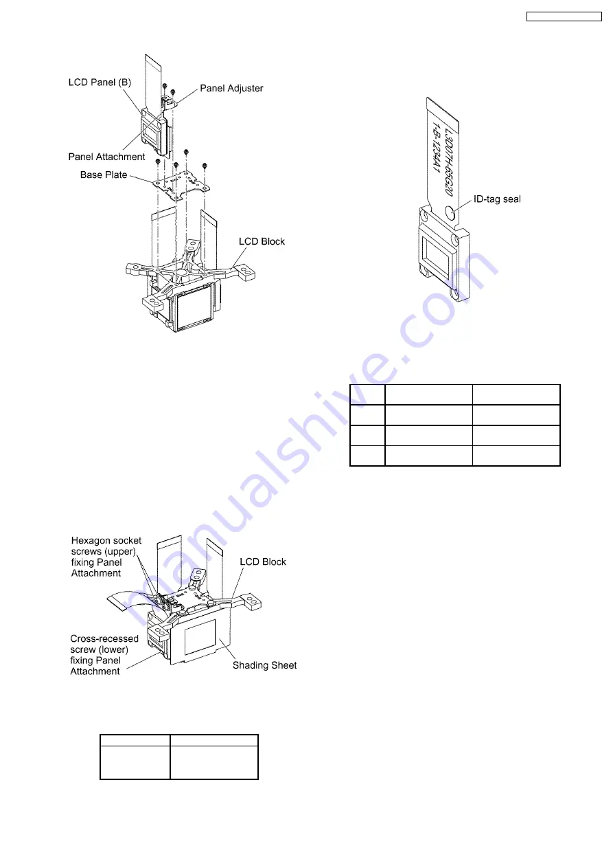
7. Reassemble
the
projector
in
the
reverse
order
of
disassembling, but leave the upper case and the screws
fixing the A-P.C.Board block as they are removed.
8. Adjust the convergence according to the section 7.4.
"Convergence Adjustment".
9. After the adjustment, while paying attention not to vary the
adjusting result, tighten the 2 screws (upper) fixing the
panel attachment temporarily with a hexagon head wrench.
Notes:
·
Prepare a hexagon head wrench processed short.
10. Remove the LCD block again.
11. Tighten the 3 screws fixing the panel attachment.
12. Adhere the shading sheet as it was.
13. Reassemble the projector as it was.
6.13. LCD Panel Discrimination
ID-tag seal color
LCD panel
Red
LCD panel (R)
Blue
LCD panel (B)
(No seal)
LCD panel (G)
·
Since the ID-tag seal is pasted to the FPC of LCD Panel,
(R), (G) or (B) can be easily identified by the color of the
seal.
·
Finally, identify the panel color by the part number printed
on the FPC.
6.14. LCD Panel Combination
·
Part number is printed on the FPC of LCD Panel.
·
When replacing LCD Panel, use a component which has
the same part number as the original.
LCD
panel
Combination1
Combination2
R
L5BDAYY00020
(L3D07H-65G20)
L5BDAYY00023
(L3D07H-66G20)
G
L5BDAYY00024
(L3D07H-66G20)
L5BDAYY00021
(L3D07H-65G20)
B
L5BDAYY00022
(L3D07H-65G20)
L5BDAYY00025
(L3D07H-66G20)
6.15. Replacement of Projection
Polarizer
·
The procedure is described as an example of projection
polarizer (B).
1. Remove the LCD block according to the section 6.10.
"Removal of LCD Block".
2. Remove the projection polarizer which requires replacing.
(The projection polarizer is secured with adhesive tape.)
Notes:
·
Be careful not to damage peripheral components
(prism, LCD panel, etc.).
·
Use tweezers.
3. Install new projection polarizer.
a. Put adhesive tape on the projection polarizer.
b. Stick the projection polarizer on the specified position.
Notes:
·
Align the projection polarizer with the guides
(lower, side) of LCD block.
·
Be careful not to touch the surface of projection
polarizer.
·
Use tweezers.
c.
Press the adhesive part and secure the projection
polarizer.
19
PT-AX100U / PT-AX100E
Summary of Contents for PT-AX100E
Page 2: ...2 PT AX100U PT AX100E ...
Page 3: ...3 PT AX100U PT AX100E ...
Page 8: ...3 2 Self Check Display and Contents 8 PT AX100U PT AX100E ...
Page 31: ...8 Troubleshooting 31 PT AX100U PT AX100E ...
Page 32: ...32 PT AX100U PT AX100E ...
Page 33: ...33 PT AX100U PT AX100E ...
Page 34: ...34 PT AX100U PT AX100E ...
Page 35: ...35 PT AX100U PT AX100E ...
Page 36: ...36 PT AX100U PT AX100E ...
Page 37: ...37 PT AX100U PT AX100E ...
Page 38: ...38 PT AX100U PT AX100E ...
Page 39: ...39 PT AX100U PT AX100E ...
Page 40: ...40 PT AX100U PT AX100E ...
Page 46: ...PT AX100U PT AX100E 46 ...
Page 47: ...11 Schematic Diagram PT AX100U PT AX100E 47 ...
Page 48: ...11 1 A P C Board 1 7 A P C Board TXANP01VKD3 1 7 PT AX100U PT AX100E 48 ...
Page 49: ...11 2 A P C Board 2 7 A P C Board TXANP01VKD3 2 7 PT AX100U PT AX100E 49 ...
Page 50: ...11 3 A P C Board 3 7 A P C Board TXANP01VKD3 3 7 PT AX100U PT AX100E 50 ...
Page 51: ...11 4 A P C Board 4 7 A P C Board TXANP01VKD3 4 7 PT AX100U PT AX100E 51 ...
Page 52: ...11 5 A P C Board 5 7 A P C Board TXANP01VKD3 5 7 PT AX100U PT AX100E 52 ...
Page 53: ...11 6 A P C Board 6 7 A P C Board TXANP01VKD3 6 7 PT AX100U PT AX100E 53 ...
Page 54: ...11 7 A P C Board 7 7 A P C Board TXANP01VKD3 7 7 PT AX100U PT AX100E 54 ...
Page 55: ...11 8 K P C Board K P C Board TNPA4047 PT AX100U PT AX100E 55 ...
Page 61: ...13 Terminal guide of ICs and transistors PT AX100U PT AX100E 61 ...
Page 62: ...14 Exploded Views PT AX100U PT AX100E 62 ...
Page 63: ...PT AX100U PT AX100E 63 ...
Page 64: ...PT AX100U PT AX100E 64 ...
Page 65: ...PT AX100U PT AX100E 65 ...


