


Care and Replacement
E
NGLISH - 27
Maintenance
Replacing the lamp unit
Before replacing the lamp unit
J
Switch off
MAIN POWER
in proper way and disconnect the power plug from the wall outlet.
Wait for more than 1 hour and make sure the lamp unit and the surroundings are cooled enough.
Unplug all the cables from the projector.
Prepare a Phillips-head screwdriver.
Contact an Authorized Service Center to purchase a replacement lamp unit (ET-LAE4000).
When the projector is mounted on the ceiling, do not work directly under the projector or put your face closer to the
projector.
NOTE:
Prior to replacing the lamp unit, allow it to cool down to prevent the risk of burns, damage and other hazards.
•
Do not attempt replacement with an unauthorized lamp unit.
•
When to replace the lamp unit
J
The lamp unit is consumable and the brightness decreases by duration of usage. The
LAMP
indicator will
inform you of the replacement timing at 1 800 hours, and at 2 000 hours, the projector will be turned off.
Those figures are rough guidance and might be shortened by the usage conditions, characteristics of the
lamp unit, environmental conditions, and so on. You can check the duration of usage time using
LAMP
RUNTIME
in the
OPTION
menu.
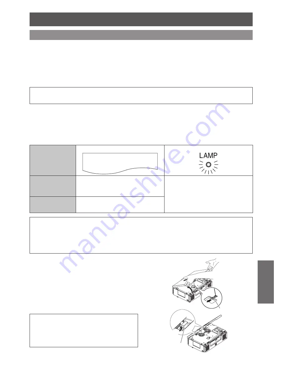
Indication
On screen
LAMP
indicator
REPLACE LAMP
Over 1 800 hours
“
REPLACE LAMP
” is displayed on the upper left
of the screen for 30 seconds.
To clear the screen immediately, press any
button.
Illuminates red.
Over 2 000 hours
“
REPLACE LAMP
” is displayed on the upper left
of the screen, and it will stay until you respond.
To clear the screen, press any button.
NOTE:
The guide times, 1 800 and 2 000 hours, are rough estimates based on certain conditions and are not guaranteed time.
•
The estimated condition is:
LAMP POWER
in
OPTION
menu set to
NORMAL
.
To prolong the lamp life, set the
•
LAMP POWER
in
OPTION
menu to
ECO-MODE
. See “LAMP POWER” in “OPTION
menu” of the functional instructions that is in the provided CD-ROM.
For more information about the lamp unit, such as guaranteed time, see the instructions which is provided with the lamp
•
unit.
J
Opening the top cover
Hold at the back corner of the top cover and
1.
slightly push up to open.
Unhook the top cover safety hook from the
2.
projector.
Hold the top cover up and press both sides of
3.
hinge parts to remove.
When the projector is mounted on the ceiling,
removing the hinge parts is not required.
Remove the top cover aside.
4.
NOTE: When the projector is mounted on
the ceiling:
Place yourself at the back side of the projector, then
•
open and close the top cover.
Do not work directly under the projector or put your
•
face close to the projector.
Hinge parts
Top cover safety hook
Press here
Summary of Contents for PT-AE4000U
Page 36: ...TQBJ0309 P1009 1109B...


