background image

E

NGLISH

-39

Useful

functions

38-E

NGLISH

NOTE:

B

After saving the adjusted settings, the “PROFILE” setting will
automatically change to the setting saved in the “PROFILE SAVE”
menu. If you continue to adjust colours to make other profiles, change
the “PROFILE” setting to “NORMAL” manually.

B

When the “COLOUR MANAGEMENT” menu is closed, or if the
“PROFILE” settings are changed before the adjusted colour settings have
been saved, the “PROFILE SAVE” confirmation screen will be displayed.
However, if you change the input signals, the adjusted colour settings will
not be saved.

LOG

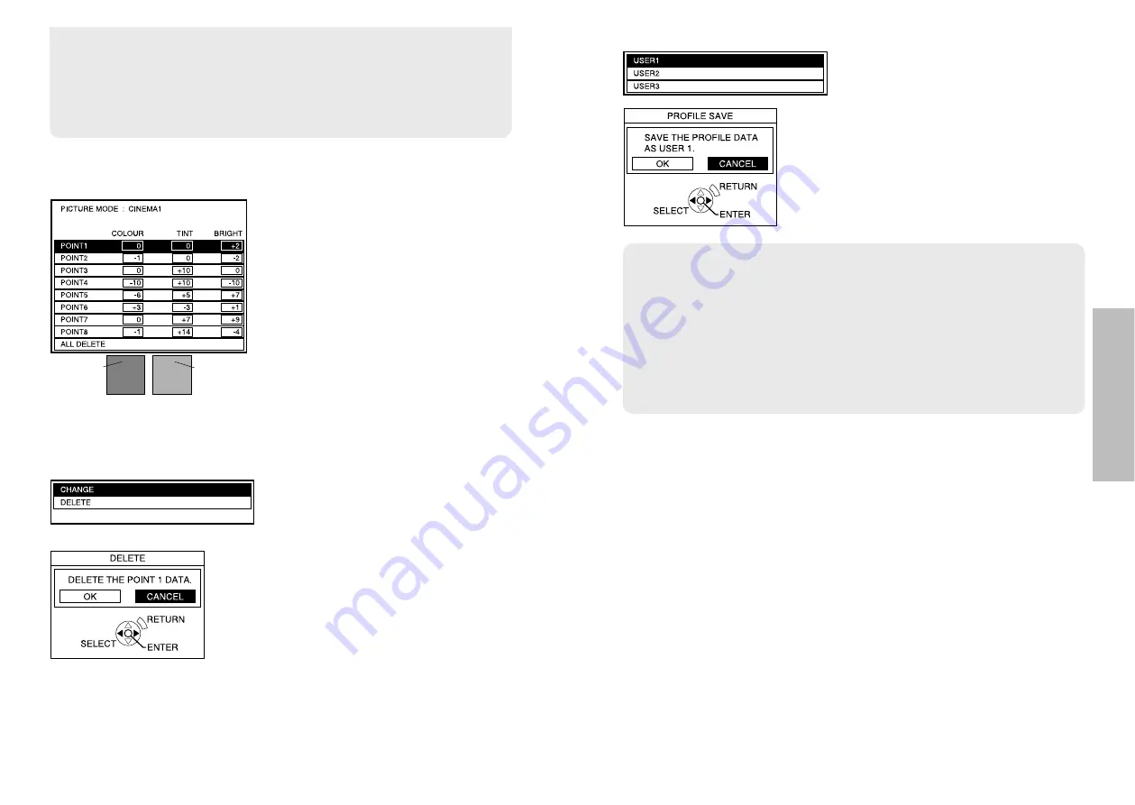
You can adjust the colour settings
again, or delete the settings.
Press the ENTER button to display the
“LOG” menu.

CHANGE

The “CURSOR” menu (page 37 

A

) will

be displayed. You can adjust the colour
settings again.

DELETE

The selected colour setting will be deleted. 
The confirmation screen will be
displayed when the ENTER button is
pressed. Select “OK” to delete the
settings.

Press the 

F

or 

G

button to select the

setting you want to adjust, and then
press the ENTER button to display the
selection screen.
To delete all the settings, select “ALL
DELETE”, and then press the ENTER
button. The confirmation screen will then
be displayed. Select “OK” and then
press the ENTER button. All the settings
in the “LOG” menu will be deleted, and
the “PROFILE” setting will return to
“NORMAL”.

Selected
colour

Adjusted
colour

PROFILE SAVE

You can save the adjusted colour
settings.
Press the ENTER button to display the
“PROFILE SAVE” menu.

Press the 

F

or 

G

button to select the

number (“USER1/2/3”) in which you
want to save the setting, and then press
the ENTER button. The confirmation
screen will then be displayed. Select
“OK” to save the setings. 

B

The colours white, gray and black cannot be adjusted.

B

If the same colours are adjusted separately, these colours may not be
adjusted to suit your preference.

B

You can adjust a maximum of 8 colours (“POINT1-8”) for each user
(“USER1/2/3”). The cursor will not be displayed when 8 colours have
already been adjusted.

Summary of Contents for PT-A900E

Page 1: ...ENGLISH TQBJ 0183 LCD Projector Operating Instructions Model No PT AE900E R Before operating this product please read the instructions carefully and save this manual for future use ...

Page 2: ... electrician Do not defeat the purpose of the earthing plug Dear Panasonic Customer This instruction booklet provides all the necessary operating information that you might require We hope it will help you to get the most out of your new product and that you will be pleased with your Panasonic LCD projector The serial number of your product may be found on its bottom You should note it in the spac...

Page 3: ...culation methods Dimensions 69 Trademark acknowledgements 70 IMPORTANT THE MOULDED PLUG U K only FOR YOUR SAFETY PLEASE READ THE FOLLOWING TEXT CAREFULLY This appliance is supplied with a moulded three pin mains plug for your safety and convenience A 13 amp fuse is fitted in this plug Should the fuse need to be replaced please ensure that the replacement fuse has a rating of 13 amps and that it is...

Page 4: ...od of time pull the mains plug out from the mains socket Do not do anything that might damage the mains lead or the mains plug BDo not damage the mains lead make any modifications to it place it near any hot objects bend it excessively twist it pull it place heavy objects on top of it or wrap it into a bundle BIf the mains lead is used while damaged electric shocks short circuits or fire may resul...

Page 5: ...oke or steam BUsing the projector under such conditions may result in fire or electric shocks When disconnecting the mains lead hold the plug not the lead BIf the mains lead itself is pulled the lead will become damaged and fire short circuits or serious electric shocks may result Always disconnect all cables before moving the projector BMoving the projector with cables still attached can damage t...

Page 6: ... places which are subject to sudden temperature changes such as near an air conditioner The life of the lamp may be shortened Do not set up the projector near high voltage power lines or near motors The projector may be subject to electromagnetic interference If installing the projector to the ceiling ask a qualified technician to carry out all installation work You will need to purchase the separ...

Page 7: ...uently turned on and off Liquid crystal panel BDo not project the same image for long periods of time as this may remain as an afterimage on the liquid crystal panel BThe liquid crystal panel of the projector is built with very high precision technology to provide fine picture details Occasionally a few non active pixels may appear on the screen as fixed points of blue green or red Please note tha...

Page 8: ...onnector is used to input signals from an S VIDEO compatible equipment such as a video deck VIDEO IN connector page 22 This connector is used to input video signals from a video equipment such as a video deck SCART connector page 22 This connector is used to input SCART signals Connector panel page 15 Air inlet port Do not cover this port Power input socket AC IN page 26 The accessory mains lead i...

Page 9: ... SHUTTER button page 34 This button is used to momentarily turn off the picture 0MEM LOAD MEMORY LOAD button page 34 This button is used to display the MEMORY LOAD menu 1C C M Cinema Colour Management button page 36 This button is used to display the COLOUR MANAGEMENT menu 2ADVANCED button pages 35 and 46 This button is used to display an item from the ADVANCED MENU 3MAIN button pages 35 and 44 Th...

Page 10: ...jector BIt is recommended that you set up the projector in a place that is tilted at less than 30 vertically Setting up the projector in places that are tilted at more than 30 vertically may shorten component life 18 ENGLISH Projector position L Projection distance SH Image height SW Image width Screen 1 01 m 40 0 50 m 1 7 0 89 m 2 11 1 2 m 3 11 2 4 m 7 10 1 27 m 50 0 62 m 2 1 11 m 3 7 1 5 m 4 11 ...

Page 11: ... is tilted vertically and keystone correction needs to be carried out place the projector so that the centre of the lens and the centre of the screen vertical are matched BProjector setting up range in relation to the screen Projector Screen Projector set up range centre of the lens BHorizontal lens shift About 25 of the screen maximum About 25 of the screen maximum When shift lever is moved to th...

Page 12: ...ment may not operate correctly for example images may not appear Connections Notes on connections BRead the instruction manual for each peripheral device carefully before connecting it BTurn off the power supply for all peripheral devices before making any connections BIf the cables necessary for connection are not included with the peripheral device or available as an option you may need to prepa...

Page 13: ...nit and the receptor the remote control unit may not operate correctly BIf strong light is allowed to shine onto the remote control signal receptor correct projector operation may not be possible Place the projector as far away from light sources as possible BIf facing the remote control unit toward the screen to operate the projector the operating range of the remote control unit will be limited ...

Page 14: ...artup logo not to be displayed set STARTUP LOGO to OFF Refer to page 52 Turn on the power of all connected devices BStart the play function of a device such as a DVD player NOTE BA rattling sound may be heard when the power is turned on and a tinkling sound may be heard when the lamp unit is turned on but these are not signs of malfunctions Power indicator 26 ENGLISH Adjusting the size BTurn the z...

Page 15: ...he picture will stop being projected The power indicator on the projector will illuminate orange while the cooling fan is still operating Press the MAIN POWER switch to turn off the power after the power indicator on the projector illuminates red BDo not cut power to the projector in any way while the cooling fan is still operating Be careful not to switch off the MAIN POWER switch of the projecto...

Page 16: ...tance in selecting a suitable aspect ratio H FIT 1 125 1 080 60i 1 125 1 080 50i 1 125 1 080 24p 750 720 60p and 750 720 50p signals only Horizontal expansion of projected image JUST Horizontal expansion of projected image Centre of image is less distorted ZOOM ZOOM1 ZOOM2 ZOOM2 is for 2 35 1 letterbox signals Expansion preserves original ratio V SCROLL XGA MXGA SXGA WIDE768 only A picture is proj...

Page 17: ...ot match the aspect ratio of the input signal it may affect the quality of viewing of the original picture BIf using this projector in places such as cafes or hotels to display programmes for a commercial purpose or for public presentation note that if the aspect ratio selection function is used to change the aspect ratio of the screen picture you may be infringing the rights of the original copyr...

Page 18: ...and the buttons to operate the selected device on the remote control unit Refer to page 17 for details Press the SHUTTER button Displaying the PICTURE menu MAIN Press the MAIN button BThe individual adjustment screen will be displayed as shown above Press the F or G button to switch the item BPress the I or H button to adjust the value or change the setting BYou can adjust PICTURE menu items using...

Page 19: ...he picture mode being selected does not match the picture mode which had been selected when that profile was saved You can only check the colour setting in the LOG menu B LOG and PROFILE SAVE are displayed only when the colours have been adjusted in CURSOR menu Using the Cinema Colour Management function C C M You can adjust save and retrieve the settings for the selected colours of the projected ...

Page 20: ...pressed Select OK to delete the settings Press the F or G button to select the setting you want to adjust and then press the ENTER button to display the selection screen To delete all the settings select ALL DELETE and then press the ENTER button The confirmation screen will then be displayed Select OK and then press the ENTER button All the settings in the LOG menu will be deleted and the PROFILE...

Page 21: ... VIDEO SCART signal is being input When a YPBPR PC HDMI signal is being input LANGUAGE menu page 50 OPTION menu page 51 BPress the MENU button to display the menu screen Refer to page 42 for details on how to operate the on screen menus POSITION menu page 48 When an S VIDEO VIDEO SCART signal is being input When a PC signal is being input When a YPBPR signal is being input When a HDMI signal is be...

Page 22: ...play does not appear and the item or function will not work even if the ENTER button is pressed Returning a setting to the factory default If you press the NORMAL button on the remote control unit you can return settings to the factory default settings However the operation of this function varies depending on which screen is being displayed B BWhen a menu screen is being displayed All the items o...

Page 23: ... only The colour is too deep I button The colour is too pale H button TINT NTSC NTSC 4 43 YPBPR PC HDMI only This adjusts the flesh tones in the picture The flesh tones are greenish I button The flesh tones are reddish H button SHARPNESS To soften the picture details I button To sharpen the picture details H button COLOUR TEMP White areas are bluish I button White areas are reddish H button DYNAMI...

Page 24: ...ton to select OK and then press the ENTER button The current picture setting will be saved MEMORY LOAD Press the ENTER button to display the MEMORY LOAD menu If any setting is not saved in the MEMORY SAVE menu the MEMORY LOAD menu will not be displayed Refer to page 34 on how to retrieve the saved settings SIGNAL MODE PC YPBPR HDMI only This displays the type of signal which is currently being pro...

Page 25: ...hed to SCART automatically and ASPECT will also be set automatically When WSS Wide Screen Signalling is detected from PAL or 625i 576i YPBPR signals the aspect ratio will also be switched automatically OFF When SCART signals are being input the input select setting and ASPECT will not be set automatically WSS will not be detected from PAL or 625i 576i YPBPR signals OVER SCAN 525p 480p 625p 576p 1 ...

Page 26: ...menu and then press the ENTER button Press the F or G button to select an item Press the I or H button to change the setting OSD DESIGN You can select the background for the OSD from 3 types TYPE1 Transparent black TYPE2 Solid blue TYPE3 Transparent navy blue OSD POSITION You can select the position where the OSD is displayed NOTE BThe setting for TV SYSTEM will also be displayed when an S VIDEO V...

Page 27: ...screen REAR When using a translucent screen OFF TIMER The projector will return to standby mode after the duration of the period you set has passed The period can be set from 60 minutes to 240 minutes in 30 minute intervals The remaining time will be displayed 3 minutes before the projector returns to standby mode The setting will be cancelled if set to OFF before reaching the duration of the peri...

Page 28: ...the necessary repairs can be made When the TEMP indicator and the LAMP indicator are illuminated There are two indicators on the control panel of the projector which give information about the operating condition of the projector These indicators illuminate or flash to warn you about problems that have occurred inside the projector so if you notice that one of the indicators is on turn off the pow...

Page 29: ...urns Notes on replacing the lamp unit BThe light generating lamp is made of glass so dropping it or allowing it to hit hard objects may cause it to burst Be careful when handling the lamp BDispose of the removed old lamp with the same care that would be taken with a fluorescent light BA Phillips screwdriver is necessary for removing the lamp unit Lamp unit replacement period The lamp is a consumab...

Page 30: ...ower on page 28 and then disconnect the mains plug from the mains socket and check that the area around the lamp unit has cooled down Use a Phillips screwdriver to turn the lamp unit cover fixing screws at the bottom of the projector and then remove the lamp unit cover Use a Phillips screwdriver to loosen the two lamp unit fixing screws until the screws turn freely Then hold the handle of the lamp...

Page 31: ...points Problem Possible cause Page Power does not turn on No picture appears The picture is fuzzy The colour is pale or grayish The remote control unit does not operate The picture does not display correctly BThe mains lead may not be connected BThe MAIN POWER switch is turned off BThe main power supply is not being supplied to the mains socket BTEMP indicator is illuminated or flashing BLAMP indi...

Page 32: ...emale R G B 0 7 V p p 75 Ω G SYNC 1 0 V p p 75 Ω HD SYNC TTL high impedance automatic positive negative polarity compatible VD TTL high impedance automatic positive negative polarity compatible COMPONENT IN Y PB CB PR CR Single line RCA pin jack x 3 Y 1 0 V p p Including sync 75 Ω PB PR CB CR 0 7 V p p 75 Ω HDMI IN Single line 19 pin HDMI connector SCART in Single line 21 pin SCART connector S VID...

Page 33: ...85 1 56 3 A PC 1 072 x 600 37 3 59 9 51 4 A PC 1 280 x 720 45 1 60 1 76 5 AA PC 1 024 x 768 48 4 60 0 65 0 A PC 1 024 x 768 56 5 70 1 75 0 A PC 1 024 x 768 60 0 75 0 78 8 A PC 1 024 x 768 68 7 85 0 94 5 A PC 1 024 x 768 72 1 89 0 99 2 A PC 1 280 x 768 45 3 56 5 76 2 A PC 1 152 x 864 64 0 71 2 94 2 A PC 1 152 x 864 67 5 74 9 108 0 A PC 1 280 x 1 024 64 0 60 0 108 0 A PC 1 360 x 768 48 8 59 8 73 8 A...

Page 34: ...from the personal computer the ER401 command will be sent from the projector to the personal computer NC NC Control commands Command Control contents Remarks In standby mode all commands other than the PON command are ignored BThe PON command is ignored during lamp ON control BIf a PON command is received while the cooling fan is operating after the lamp has switched off the lamp is not turned bac...

Page 35: ...TE specifications Command Inquiry contents Parameter 000 OFF 001 ON VID VIDEO SVD S VIDEO RG1 PC YUV YPBPR SCT SCART HDM HDMI Power condition QPW Input signal QIN Picture mode QPM NAT NATURAL NOR NORMAL DYN DYNAMIC CN1 CINEMA1 CN2 CINEMA2 CN3 CINEMA3 VID VIDEO Refer to page 33 for details Shutter function QSH 0 OFF 1 ON Freeze function QFZ 0 OFF 1 ON Inquiry commands 54 2 1 8 335 13 3 16 82 9 3 1 ...

Page 36: ... with general household waste For proper treatment recovery and recycling please take these products to designated collection points where they will be accepted on a free of charge basis Alternatively in some countries you may be able to return your products to your local retailer upon the purchase of an equivalent new product Disposing of this product correctly will help to save valuable resource...

Reviews: