background image

Communication Failure

   Is the UTP/fiber cable connected to the correct port?

  Are the SFP modules complied with the same standard each other?

 Is the fiber cable correct the fiber mode (single or multi)?

Attempt to disable “EEE conforming to IEEE802.3az (LPI)” function at target port.


Are the communication speed and mode settings correct?

If the communication mode signal cannot be properly obtained, the Ethernet Switch
operates in half-duplex mode. Check the auto negotiation setting again.
Do not fix the speed/duplex mode of the connected terminal to full-duplex mode.

   Is the usage rate of the network to which this Ethernet Switch is connected excessively     


high?
Try separating this Ethernet Switch from the network.

Stacking Failure

   Is the stacking function enabled?

   Is the 40G direct attached cable connected to stacking port (port 29 or 30) correctly?

   Is the STACK ID LED displayed the correct ID?


Are the port LEDs lit up orange?
If the port LEDs are lit up orange, the ports will be blocked via the loop detection 
and blocking functions. After the port controlled loop connections are resolved, 
release the port blocking from the settings screen as to whether the standby time 
will be longer than the recovery time until the auto-recovery of the loop detection 
and blocking.


   Are all of the firmware versions for the devices that are connected to the stacks 

identical?

24

Troubleshooting

* Please refer to the instruction manual on the ZEQUO assist Plus 

on Panasonic’s website in regard to settings and management 
methods.

Summary of Contents for PN36241E-ID

Page 1: ...red by the warranty I1017 20122 ZEQUO 6600RE Model No Installation Guide Printed in Japan PN36241E TH PN36241E MY PN36241E ID PN36241E SG PN36241E NZ 2 12 7 Higashi Shimbashi Minato ku Tokyo Japan 105 0021 Panasonic Electric Works Networks Co Ltd Panasonic Electric Works Networks Co Ltd 2022 The instruction manuals Web Version and CLI Version latest firmware and SDN application ZEQUO assist Plus c...

Page 2: ...asic operation 2 Part Names and Functions 3 Installation and Configuration 3 1 Removing Mounting and Replacing the Power Modules 3 6 7 7 8 10 11 12 15 15 3 2 Removing Mounting and Replacing the Fan Modules 17 3 4 Installing on level shelves 20 3 3 Grounding Cable Connection 19 3 5 Mounting to rack 3 6 Configuration of IP address Basic Troubleshooting 20 21 23 ...

Page 3: ...ings or boards Do not use the Ethernet Switch in very dusty areas such as on floors underneath floors the backside of ceilings or boards Deviation could lead to fire electrical shock and or equipment failure It is recommended that the Ethernet Switch be operated in environments such as the inside of racks where it is difficult for dust to be generated Do not store or use the Ethernet Switch in pla...

Page 4: ...er modules except for our optional SFP module PN54021K PN54023K and the SFP module PN59021 PN59023 to the SFP extension slots Do not insert any other modules except for our optional SFP module PN54021K PN54023K SFP module PN59021 PN59023 or 40G direct attach cable OP 40G T01 OP 40G T02 to the stacking ports Port29 30 Check out our website for the latest information on supported SFP modules Do not ...

Page 5: ...ble means to ensure safety and reliability This Ethernet Switch is not designed nor manufactured with the intention that it be used for applications in use with railways aviation and medical care etc where the influence rate due to communication failures is extremely high in regard to systems that directly affect systems and human lives which require extremely high reliability It is recommended th...

Page 6: ...h the specification High humidity Possible spilled liquid water Dusty Possible static charge such as carpet Under direct sunlight Possible condensation High low temperature exceeding the specifications environment Strong vibration and or strong shock Please use this Ethernet Switch in place where ambient temperature is from 0 to 45 C Failure to meet the above conditions may result in fire electric...

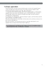
Page 7: ...ctions are feasible for up to a maximum of four units whereas the ZEQUO 6700RE or the ZEQUO 6600RE are mixed 7 The ZEQUO 6600RE is a Layer 3 all giga Ethernet Switch equipped with management functions that has 24 10 100 1000BASE T ports 4 SFP expansion ports 4 SFP expansion ports and 2 40G stack ports The ports which generated the loops give notification via LEDs and the ports which generated the ...

Page 8: ... IPv4 L2 L3 Access control Management DHCP relay agent DHCP server Console TELNET SSH WEB SNMPv1 v2c v3 ZEQUO assist Plus Power supply AC 100 240 V 50 60 Hz 2 5 A 8 Product Outline 1 Stack ports 2 ports ports 29 30 Options 40G direct attach cable 1 m Order model number OP 40G T01 40G direct attach cable 2 m Order model number OP 40G T02 Fan module slots 2 slots Supported fan module model PN73002 F...

Page 9: ...e environment Temperature 20 70 C Humidity 10 90 RH no condensation Mass Weight 5 000 g One power module is mounted into either power slot 1 or 2 default 5 600 g Two power modules are mounted into both power slot 1 and 2 External dimensions 44 mm Height 440 mm Width 312 mm Depth Excluding protruding sections Operating environment Temperature 0 45 C Humidity 20 80 RH no condensation Fan Installed 9...

Page 10: ...ntents are insufficient Quantity Power module blank panel 1 unit mounted Fan module PN73002 FAN02 Module 2 unit mounted Power module 70002 RP02 200W Module 1 unit mounted 40G Direct attach cable OPQSFP T01 1 Optional accessories PN54021K XX 1000BASE SX SFP Module PN54023K XX 1000BASE LX SFP Module PN59021 XX 10GBASE SR SFP Module PN59023 XX 10GBASE LR SFP Module PN73002 FAN02 Module 70002 XX RP02 ...

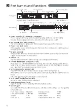
Page 11: ... of the LEDs light up green the STATUS LED lights up orange and the hardware s self diagnostic is implemented On completion of self diagnosis STATUS LED light in green and the Ethernet Switch starts operation as a Ethernet Switch When this Ethernet Switch successfully communicates with a terminal connected to a port the Port LED lights up When the terminal is not operating normally for example whe...

Page 12: ...ts can be stacked by 40G direct attach cables Console port Connect a VT100 compatible terminal etc with this port to configure or manage this Ethernet Switch Transmission mode RS 232C Transmission speed 9 600 bps Stop bit 1 bit Flow control None Emulation mode VT100 Data length 8 bits Parity control None Transmission connector RJ45 Ground terminal Only qualified personnel should install minimum 18...

Page 13: ...ff due to loop detection and shutoff functions storm controls BPDU guard Transmitting and receiving just the administration packets Orange Light Orange Blink Off No devices are connected Port LED SFP Port 21 24 Green Light Link is established at 1000 Mbps Green Blink Transmitting and receiving data at 1000 Mbps Shutting off due to loop detection and shutoff functions storm controls BPDU guard Tran...

Page 14: ... and receiving data at 1000 Mbps or 10 Gbps Orange Light Orange Blink Off No devices are connected Port LED STACK port 29 30 Shuts off due to loop detection and shutoff functions storm controls BPDU guard Transmitting and receiving just the administration packets Green Light Link is established at 40 Gbps Green Blink Transmitting and receiving data at 40 Gbps Orange Light Orange Blink Off No devic...

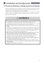
Page 15: ...ithout them being attached that might cause injuries via the mechanical parts malfunctions due to the incursion of foreign objects breakage due to temperature rises in the internal components the misoperations of other devices due to the effects of electronic interference from this product the misoperations of other devices due to the effects of electronic interference etc When removing mounting a...

Page 16: ... the power module while supporting it 16 Removing the power module Step 1 Remove the blank panel on the power module slot Carefully store the removed blank panel Step 2 Insert the power module into the power module slot until a clunk is heard Step 3 Attach the power cord on to the power module Step 4 Make sure that the power status LED of the power module and the POWER1 LED the POWER2 LED or both ...

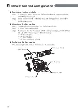
Page 17: ...ration remove and mount the fan module within 3 minutes Since the air flow cannot be assured the internal temperatures will rise and that might cause malfunction When the fan module is not mounted prevent foreign objects from incurring inside as well as operators from getting inside of the product unit through the fan slots Might cause injuries via the mechanical components etc or malfunctions due...

Page 18: ...Slowly insert the fan module into the fan module slot Step 2 Tighten the retainer screws Step 3 Make sure that the status LED is NOT blinking in orange and the STACK ID LED is NOT displaying any of the followings 11 Fan 1 failure 12 Fan 2 failure 13 Fan 1 and Fan 2 failures Mounting the fan module After removing the fan module then mount the fan module Replacing the fan module Fan module slot Fan ...

Page 19: ... be no less than 18 AWG and the length is 50 cm 3 The ground installed screw shall comply with 3 5mm minimum in nominal thread diameter and engage at least two complete threads into metal chassis with appropriate fixing hardware like washer 4 The grounding cable shall not be removed during normal operation servicing or maintenance 5 Installation steps Step 1 Ensure the detachable power supply cord...

Page 20: ...t Switch firmly to the rack using the supplied 4 screws for 19 inch rack or screws furnished at the rack The main unit can be placed 20 mm back on the rack by changing the bracket fixing position 20 mm 3 4 Installing on level shelves 1 Apply the supplied rubber feet onto the bottom surface of the unit 2 Install in a level area Caution Do not stack and use Set up with a clearance of 20 mm or more B...

Page 21: ...ed Screen 2 4 Enter the IP address and subnet mask using the following command Screen 3 enable configure config interface vlan1 config if ip address 192 168 1 254 255 255 255 0 5 Enter the following command to save the setting Since the following screen is displayed enter Y and the settings will be saved Screen 4 config if exit config exit copy running config startup config 6 From terminals connec...

Page 22: ...he PDF version of the Operating Instructions on Panasonic s website Detailed configuration and management methods using the CLI Configuration and management method from ZEQUO assist Plus 2 n e e r c S 4 n e e r c S 3 n e e r c S 22 Installation and Configuration 3 ...

Page 23: ...the power port Use the Ethernet Switch within the range of operating temperature is firmly inserted If the STATUS LEDs are blinking orange If the STATUS LEDs are blinking green Are power modules 1 and 2 properly mounted If they are malfunctioning or not properly mounted the STACK ID LED will display P Check whether or not the power modules are securely connected Are the fan modules properly mounte...

Page 24: ...h Try separating this Ethernet Switch from the network Stacking Failure Is the stacking function enabled Is the 40G direct attached cable connected to stacking port port 29 or 30 correctly Is the STACK ID LED displayed the correct ID Are the port LEDs lit up orange If the port LEDs are lit up orange the ports will be blocked via the loop detection and blocking functions After the port controlled l...

Reviews: