


4. To prevent an X-Radiation possibly, it is essential to use the
specified picture tube.
HORIZONTAL OSCILLATOR DISABLE CIRCUIT TEST SERVICE WARNING :
The test must be made as a final check before set is returned to the customer.
CONFIRMATION OF X-RAY MOVEMENT
1. Turn off TV set.
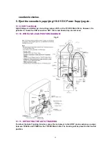
2. Connect the circuit below between TP1209 and TP1208.
Figure 2
3. Turn on DC Power, and then turn on the set. Confirm that the
picture is on the screen properly.
4. Confirm that the picture goes out of horizontal sync while getting
down the voltage to DC Power.
5. If this does not occur even when getting down the voltage of DC
Power to 0 V, it means that X-ray protect circuit is not operating.
Further confirmation and repair is required.
REPAIR PROCEDURES OF HORIZONTAL OSCILLATOR DISABLE CIRCUIT
1. Connect a DC voltmeter between capacitor C513 (+) on the Main
circuit board and chassis ground.
2. If approx23.5 V is not present at that point when 120 V AC
is applied, find the cause. Check R503, R5505, C5507, C513 and
D503.
3. Carefully check above specified parts and related circuits and
parts. When the circuit is repaired, try the horizontal oscillator
disable circuit test again.
CIRCUIT EXPLANATION
HORIZONTAL OSCILLATOR DISABLE CIRCUIT
The positive DC voltage, supplied from the D503 cathode for monitoring high voltage, is applied
to the IC5301 Pin11 through R503 and R5504. Under normal conditions, the voltage at IC5301 Pin
11 is less than approx 6 V. If the highvoltage at Flyback Tr Pin 5 exceeds the specified voltage,
the positive DC voltage which is supplied from the D503 cathode also increases. The increased
voltage is applied to IC5301 Pin11 through R503 and R5504. Due to the increased voltage at
IC5301Pin11, the horizontal oscillator frequency increases, the picture goes out of horizontal
sync, the beam current decreases and the picture becomes dark in order to keep X-radiation
under specification.
5
Summary of Contents for Omnivision PV-C2540-K
Page 8: ...Fig 1 3 Fig 1 4 8 ...
Page 25: ...Fig D5 6 1 2 1 Notes in chart 25 ...
Page 28: ...6 2 2 Inner Parts Location Fig J1 1 28 ...
Page 29: ...6 2 3 EJECT Position Confirmation Fig J1 2 29 ...
Page 30: ...6 2 4 Grounding Plate Unit Full Erase Head and Cylinder Unit Fig J2 1 30 ...
Page 43: ...6 3 CASSETTE UP ASS Y SECTION 6 3 1 Top Plate Wiper Arm Unit and Holder Unit Fig K1 1 43 ...
Page 74: ...74 ...
Page 78: ...11 2 MECHANISM BOTTOM SECTION 78 ...
Page 79: ...11 3 CASSETTE UP COMPARTMENT SECTION 79 ...
Page 80: ...11 4 CHASSIS FRAME SECTION 1 80 ...
Page 81: ...11 5 CHASSIS FRAME SECTION 2 81 ...
Page 82: ...11 6 PACKING PARTS AND ACCESSORIES SECTION 82 ...