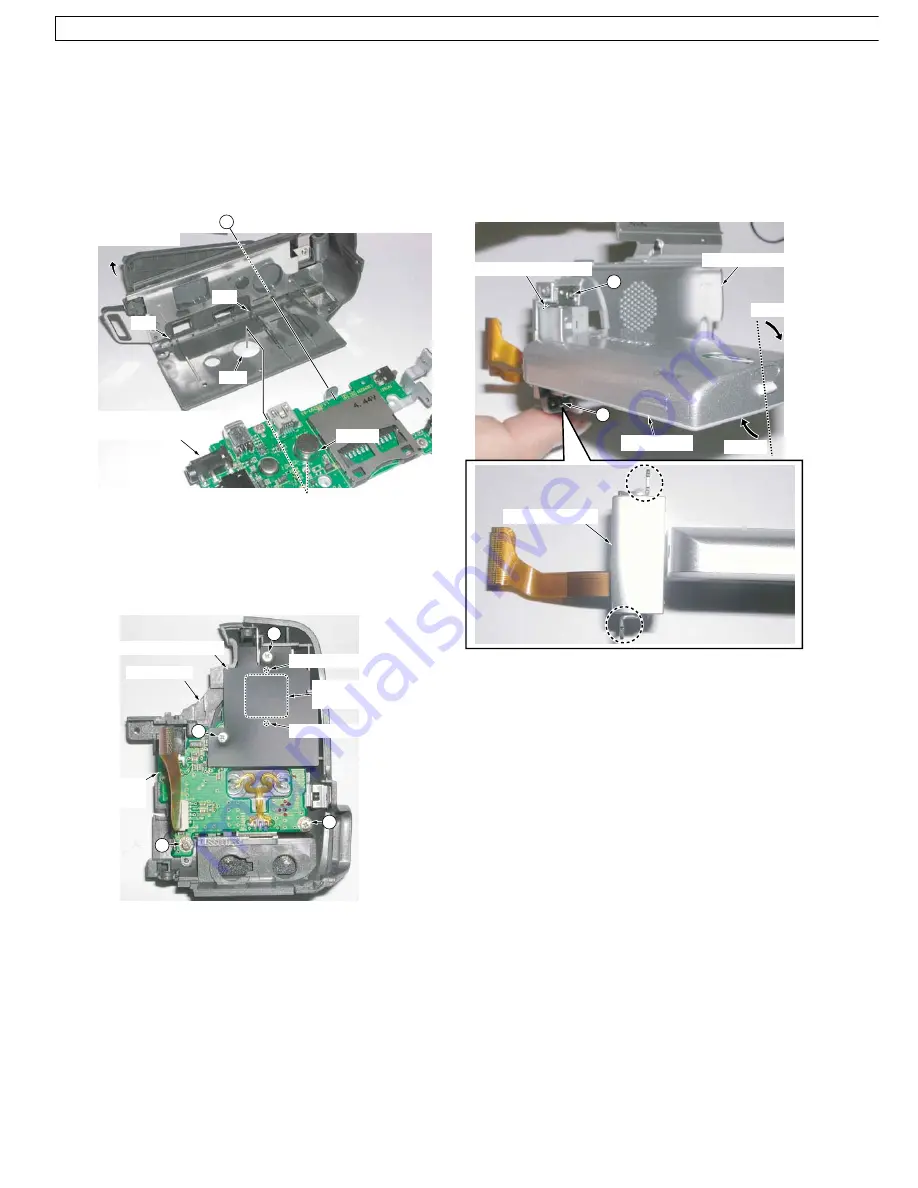
11. Removal of Side Case R Unit
Open and rotate the LCD to access the 2 Screws (419, 457)
as shown below, then remove it.
Installation of Side Case R Unit
When installing, note to the direction of the Shaft Case
Unit. Be sure to install the LCD (Ass'y) into the Side Case
R Unit with the LCD rotated as shown. Otherwise, the LCD
open/close switch on the Side Case R Unit will be damaged.
Fig. D11
LCD (Ass'y)
Side Case R Unit
Rotate
Rotate
LCD open/close SW.
419
457
Shaft Case Unit
9. Removal of Jack C.B.A. & Bottom Angle Ass'y
1) Open the L Cover.
2) Remove the Screw (450) and release the Tripod Portion
from the hole.
Installation of Jack C.B.A. & Bottom Angle Ass'y
Insert both the Jack C.B.A. & Bottom Angle Ass'y into the
2 slots and secure the Tripod into the hole.
Fig. D9
10. Installation of Front C.B.A.
1) Install the Four Eyes Lens (For model with Light) into
the Front Case. Then, install the Front C.B.A. with 2
bosses of the Four Eyes Lens and 2 Screws (533).
2) Install the Light Shield Sheet with 2 Screws (533).
Fig. D10
Jack C.B.A. &
Bottom Angle Ass'y
Tripod
slot
slot
Open L Cover
hole
450
Front
C.B.A.
Light Shield Sheet
boss (For model with Light)
boss (For model with Light)
Four Eyes Lens
(For model with Light)
Front Case
533
533
533
533
48
NV-GS6EE / NV-GS6GC / NV-GS17E / NV-GS17EB / NV-GS17EF / NV-GS17EG / NV-GS17EP / NV-GS18E / NV-GS21E / NV-GS21EB / NV-GS21EG / NV-GS21EK / NV-GS21EP / NV-GS25GC / NV-GS25GN /
GS28GK / NV-GS35E / NV-GS35EB / NV-GS35EG / NV-GS35EP / NV-GS35GC / NV-GS35GN / NV-GS38GK


