last are displayed.
Making the mode dial of This Machine a pc connection mode push [BACK LIGHT] button and
[REW
] button and [PHOTO SHOT] button simultaneously for 3 seconds with no SD
Card inserted.
The Service Menu will be displayed.
NOTE:
In the case that a tape is included the above operation does not work.
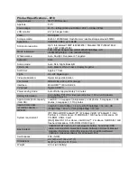
Self diagnosis cord contents are as follows
Display position
Cord specification
Display contents(Self diagnosis cord contents)
Mechanism & Lens motor lock code
DISPLAY
CONDITION
01
T-REEL LOCK
02
S-REEL LOCK
03
UNLOADING LOCK
04
LOADING LOCK
05
SYLINDER
51
ZOOMMOTOR LOCK
52
FOCUSMOTOR LOCK
Turn off the power supply after confirmation,
Please do the error cord backup record the clear after repair completion.
CLEAR METHOD
Making the mode dial of This Machine a pc connection mode push [BACK LIGHT] button and
[REW
] button and [RECORDING START/STOP] button simultaneously for 3 seconds
(with noSD Card inserted).
NOTE:
1. When an Error Display “PUSH THE RESET SWITCH” on the
monitor, it is not necessary to push the MENU button to enter the
41
Summary of Contents for NV-GS120EB
Page 8: ...4 2 DISASSEMBLY PROCEDURES Flow Chart for Disassembly Procedure 8 ...
Page 12: ...Fig D3 Fig D4 12 ...
Page 13: ...Fig D5 Fig D6 13 ...
Page 14: ...Fig D7 Fig D8 14 ...
Page 15: ...Fig D9 Fig D10 15 ...
Page 16: ...Fig D11 Fig D12 16 ...
Page 17: ...Fig D13 Fig D14 17 ...
Page 18: ...Fig D15 18 ...
Page 19: ...Fig D16 19 ...
Page 20: ...Fig D17 Fig D18 20 ...
Page 21: ...Fig D19 Fig D20 21 ...
Page 22: ...Fig D21 Fig D22 22 ...
Page 23: ...Fig D23 Fig D24 23 ...
Page 24: ...Fig D25 Fig D26 24 ...
Page 25: ...Fig D27 Fig D28 Fig D29 25 ...
Page 28: ...Fig M4 Fig M5 28 ...
Page 30: ...Fig L2 5 SERVICE CAUTION 5 1 HOW TO DISCHARGE THE CAPACITOR ON FRONT C B A 30 ...
Page 34: ...Fig E4 34 ...
Page 44: ...12 2 FRAME CASING SECTION 2 44 ...
Page 45: ...12 3 LCD SECTION 45 ...
Page 46: ...12 4 CAMERA LENS SECTION 46 ...
Page 47: ...12 5 VCR MECHANISM SECTION 47 ...
Page 48: ...12 6 PACKING PARTS ACCESSORIES SECTION 48 ...
Page 49: ...13 REPLACEMENT PARTS LIST 13 1 FRAME CASING SECTION 1 2 PARTS LIST 49 ...
Page 62: ...62 ...
Page 71: ... VEP001C6A COMPONENT SIDE FOIL SIDE NV GS200SERIES GS120SERIES JACK C B A 1 A B C D E 2 3 4 5 ...
Page 103: ...50 ...
Page 104: ...50 ...
Page 107: ... VEP001C2B COMPONENT SIDE FOIL SIDE 1 A B C 2 3 4 5 NV GS200SERIES GS120SERIES SD OPEN C B A ...
Page 111: ... FOIL SIDE COMPONENT SIDE PP301 PS201 FP3402 FP701 ...
Page 112: ...PP301 PS201 FP3402 FP701 FP4002 FOIL SIDE COMPONENT SIDE ...
Page 120: ... VEP29159A COMPONENT SIDE FOIL SIDE 1 A B 2 3 4 5 NV GS200SERIES GS120SERIES EVF C B A ...


