34
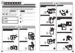
5. While unhooking the rib at the upper center of PCB box
by inserting the screwdriver, draw out the PCB box
toward you.
6. Unhook the connector’s hook, then disconnect the con-
nectors.
7. Main PCB Assy (Main PCB with PCB box)
9.4.
Air Flow Ins. PC
1. First, remove the Glass Shelves, Bottle Support and
Drawers, then unscrew the two screws.
2. Remove the PC Air Duct Lower.
Summary of Contents for NR-BN34FX1
Page 2: ...2 1 Safety Precautions ...
Page 3: ...3 ...
Page 4: ...4 ...
Page 8: ...8 4 Location of Controls and Components 4 1 Display and Control Panel ...
Page 9: ...9 4 2 Components ...
Page 10: ...10 5 Installation Instructions ...
Page 11: ...11 ...
Page 13: ...13 6 2 2 Super Cool Mode 6 2 3 Super Freeze Mode 6 2 4 Flash Freeze Mode ...
Page 14: ...14 6 2 5 ECO Mode 6 2 6 Holiday Mode 6 2 7 Alarm Mode 6 2 8 Child safety lock ...
Page 16: ...16 7 1 1 How to start 7 1 2 How to stop 7 1 3 Summary of Service Mode ...
Page 17: ...17 7 1 4 Service Mode 00 Main PCB 7 1 5 Service Mode 01 Display Panel PCB ...
Page 18: ...18 7 1 6 Service Mode 02 Compressor 7 1 7 Service Mode 03 Fan Motor ...
Page 19: ...19 7 1 8 Service Mode 04 Defrost Heater 7 1 9 Service Mode 05 PC Damper ...
Page 20: ...20 7 1 10 Service Mode 06 LED Lamp 7 1 11 Service Mode 07 PC Temp Sensor ...
Page 21: ...21 7 1 12 Service Mode 08 FC Temp Sensor 7 1 13 Service Mode 09 Defrost Sensor ...
Page 22: ...22 7 1 14 Service Mode 10 Vitamin LED ...
Page 26: ...26 8 Troubleshooting Guide 8 1 Not cooling at all Both PC FC compressor does not operate ...
Page 27: ...27 8 2 PC is not cooling or poor cooling FC cooling condition is normal ...
Page 28: ...28 8 3 FC is not cooling Compressor operate ...
Page 29: ...29 8 4 Cooling system trouble ...
Page 30: ...30 8 5 Communication trouble 8 6 Temperature sensor trouble ...
Page 31: ...31 ...
Page 37: ...37 4 Unhook the hook then remove the Door Switch FC 5 Disconnect the connector ...
Page 39: ...39 9 8 Positions of Temperature Sensors Thermal Fuse Defrost Heater and PC Door Switch ...
Page 44: ...44 33 Screw the Handles to the right side 34 Install the Filling Plugs to the left side ...


