background image

10.4. PARTS LIST

10.4.1. NN-SD798S

Ref. No.

Part No.

Part Name & Description

Pcs/Set

Remarks

BZ210

L0DDEA000014

BUZZER

1

2.0KHz

C13

AECETS1C100B

AL CHEM CAPACITOR

1

10µF/16V

C111

ECEA1EKS101I

AL CHEM CAPACITOR

1

100µF/25V

C10

AECETK1V102B

AL CHEM CAPACITOR

1

1000µF/35V

C482

AECETS1H010B

AL CHEM CAPACITOR

1

1µF/50V

C483

AECETS1HR47B

AL CHEM CAPACITOR

1

0.47µF/50V

C485

AECETS1H2R2B

AL CHEM CAPACITOR

1

2.2µF/16V

C112

ECQV1H474JL2

METAL FILM CAPACITOR

1

0.47µF/50V

CX320

H2B800400007

CERAMIC RESONATOR

1

8.0MHz

DISP

A2BB00000150

VACUUM FLUORESCENCE DISPLAY

1

DISP HOLDER

F66176Z00AP

LCD HOLDER

1

F64578P00AP

FILTER SHEET

1

D40,D220,D222,D223,D226

MA2C19600E

DIODE

5

D10-D13,D110,D111

B0EAKT000025

DIODE

6

D100

MA2C700A0F

DIODE

1

D130-D133

AE3294UBCA7

LED

4

IC1

MN101C88DAH

L.S.I.

1

IC10

C0CAADG00060

IC

1

IC350

C0EBH0000264

IC

1

IC480

C0ABBA000230

IC

1

Q131

B1BAAJ000003

TRANSISTOR

1

D25

D4EAY271A036

ZENER RESISTOR

1

270V

D26,D27

D4EAY112A036

ZENER RESISTOR

2

1100V

R211

D0AE102JA155

CARBON FILM RESISTOR

1

1K,1/4W,5%

R10

D0AE103JA155

CARBON FILM RESISTOR

1

10K,1/4W,5%

R100

D0AE104JA155

CARBON FILM RESISTOR

1

100K,1/4W,5%

R123

D0AE241JA155

CARBON FILM RESISTOR

1

240

,1/4W,5%

R220

D0AE271JA155

CARBON FILM RESISTOR

1

270

,1/4W,5%

R124

D0AE470JA155

CARBON FILM RESISTOR

1

47

,1/4W,5%

R229

D0AE680JA155

CARBON FILM RESISTOR

1

68

,1/4W,5%

RY1

AEBGJQC25F18

POWER RELAY

1

RY2

K6B1AZA00011

POWER RELAY

1

T10

G4C3AAD00006

LOW VOLTAGE TRANSFORMER

1

120V

VZ490

D3BB6103A006

VARISTOR

1

RE80

EVEJ1HF2224B

REVOLVING ENCODER

1

SW40-SW44,SW46-SW51

EVQ11L05R

SWITCH

11

ZD110

B0BA3R500006

ZENER DIODE

1

ZD220

B0BA01100004

ZENER DIODE

1

10.4.2. NN-ST778S

Ref. No.

Part No.

Part Name & Description

Pcs/Set

Remarks

BZ210

L0DDEA000014

BUZZER

1

2.0KHz

C12

AECETK1V471B

AL CHEM CAPACITOR

1

470µF/35V

C13,C16

AECETS1C220B

AL CHEM CAPACITOR

2

22µF/16V

CX320

H2B800400007

CERAMIC RESONATOR

1

8.0MHz

DISP110

L5AAAEC00057

LCD

1

DISP HOLDER

F66174U20AP

LCD HOLDER

1

D220-D222,D224.D225,D227

MA2C19600E

DIODE

6

D10-D13

B0EAKT000025

DIODE

4

IC1

MN101C78AEH

L.S.I.

1

IC350

C0EBE0000401

IC

1

Q10,Q180

B1BAAJ000003

TRANSISTOR

2

D25

D4EAY271A036

ZENER RESISTOR

1

270V

D26,D27

D4EAY112A036

ZENER RESISTOR

2

1100V

R211

D0AE102JA155

CARBON FILM RESISTOR

1

1K,1/4W,5%

R228,R352

D0AE104JA155

CARBON FILM RESISTOR

2

100K,1/4W,5%

R210

D0AE332JA155

CARBON FILM RESISTOR

1

3.3K,1/4W,5%

R225

D0AE470JA155

CARBON FILM RESISTOR

1

47

,1/4W,5%

RY1

AEBGJQC25F18

POWER RELAY

1

RY2

K6B1AZA00011

POWER RELAY

1

T10

G4C2AAD00006

LOW VOLTAGE TRANSFORMER

1

120V

VZ1

D3CA6103A017

VARISTOR

1

10K

ZD10

B0BA5R600016

ZENER DIODE

1

ZD11

B0BA4R400002

ZENER DIODE

1

39

NN-SD798S / NN-ST778S / NN-SA768W

Summary of Contents for NN-SD798S

Page 1: ...ppliances Microwave Oven Shanghai Co Ltd All rights reserved Unauthorized copying and distribution is a violation of law NN SD798S NN ST778S NN SA768W RPH LATIN AMERICA RUH MEXICO Microwave Oven ORDER...

Page 2: ...2 NN SD798S NN ST778S NN SA768W...

Page 3: ...3 NN SD798S NN ST778S NN SA768W...

Page 4: ...nterlock Switch 14 5 3 Magnetron 14 5 4 key board membrane Membrane switch assembly 14 5 5 Inverter power supply U 15 5 6 Temperature thermistor 15 6 MEASUREMENTS AND ADJUSTMENTS 16 6 1 Adjustment of...

Page 5: ...1 SCHEMATIC DIAGRAM 5 NN SD798S NN ST778S NN SA768W...

Page 6: ...e microcomputer in the DPC to determine operating conditions and output necessary to control PWM signal to the Inverter Power Supply for control of the output power 2 3 Inverter defrost When the Auto...

Page 7: ...d the Auto program selected is Oatmeal T2 T1 K 2 min and 40 sec 0 1 160sec 0 1 16 sec Category P1 Power P2 Power K Factor Standard Omelet MEDIUM MEDIUM 0 2 2 5 Sensor reheat Only for sensor models Aut...

Page 8: ...inum heat sink may be HOT due to heat energy therefore extreme care should be taken during servicing H V Inverter warning WARNING FOR INVERTER POWER SUPPLY U GROUNDING Check the High Voltage Inverter...

Page 9: ...on Never insert a wire nail or any other metal object through the lamp holes on the cavity or any holes or gaps because such objects may work as an antenna and cause microwave leakage 3 6 Verification...

Page 10: ...tors from D P C 2 Remove 1 grounding screw 3 Disconnect connector CN701 on H V Inverter board 4 Remove 1 screw holding escutcheon base and slide the escutcheon base upward slightly 5 Remove all screws...

Page 11: ...fice 4 5 Door assembly 1 Remove door C from door E by carefully pulling outward starting from upper right hand corner using a flat blade screwdriver 2 Separate door E from tabs on door A and remove do...

Page 12: ...OTE After reinstalling the new turntable motor and reconnecting the 2 lead wires reinstall the motor cover by rotating it around 180 tucking the 2 tabs under the base in the 2 provided slots then scre...

Page 13: ...ecause it is hot 1 Discharge high voltage charge 2 Remove the H V lead wire from magnetron terminals 3 Disconnect 2 connectors from CN701 CN702 on H V Inverter U 4 Remove 1 screw holding grounding pla...

Page 14: ...erlock Switch 1 Unplug lead wires from Inverter Power Supply U primary terminals 2 Connect test probes of ohm meter to the disconnected leads that were connected to Inverter Power Supply U 3 Test the...

Page 15: ...stops in 37 seconds after started Test 2 Continued from Test 1 1 Unplug the oven s AC power supply cord from outlet 2 Unplug 3 pin connector CN701 CN703 remains unplugged 3 Plug in the oven s AC power...

Page 16: ...all latch switches again by following the component test procedures 6 2 Measurement of microwave output The output power of the magnetron can be determined by performing IEC standard test procedures H...

Page 17: ...the start button or set the timer and with the magnetron oscillating measure the leakage by holding the probe perpendicular to the surface being measured 7 2 1 Measurement with the outer panel remove...

Page 18: ...7 4 At least once a year have the radiation monitor checked for calibration by its manufacturer 18 NN SD798S NN ST778S NN SA768W...

Page 19: ...body 7 120V AC is present on the digital programmer circuit Terminals of power relay s and primary circuit of Digital Programmer Circuit When troubleshooting be cautious of possible electrical shock h...

Page 20: ...ch switches 2 Open or loose connection of high voltage circuit especially magnetron filament circuit NOTE Large contact resistance will cause lower magnetron filament voltage and cause magnetron to ha...

Page 21: ...st you must program the DPC into TEST MODE press Clock pad once press Timer pad once Press Start pad once press Power Level pad once Program unit for operation H95 H97 H98 H99 appears in display windo...

Page 22: ...netron wiring between Inverter and magnetron terminal 2 Between 1 0A and 2 0A Check continuity of D702 in Inverter PCB 1 D702 shorted Replace H V Inverter F606Y8M00AP 2 D702 is OK Replace magnetron Sh...

Page 23: ...8 6 How to check the semiconductors using an OHM meter 23 NN SD798S NN ST778S NN SA768W...

Page 24: ...9 EXPLODED VIEW AND PARTS LIST 9 1 EXPLODED VIEW 24 NN SD798S NN ST778S NN SA768W...

Page 25: ...0 HOOK LEVER A 1 15 F31374650AP HOOK LEVER B 1 16 F31384650AP HOOK LEVER C 1 17 F400A4T00AP FAN MOTOR 1 AC120V SINGLE PHASE 60Hz 18 F40084T00AP FAN BLADE 1 19 F40254W00AP AIR GUIDE A 1 20 F40264T60APG...

Page 26: ...Ref No Part No Part Name Description Pcs Set Remarks 49 F04468Y30RP FUNCTION LABEL 1 SD798S 52 F00066G00RP CAUTION LABEL 1 SD798S RPH ST778S RPH 26 NN SD798S NN ST778S NN SA768W...

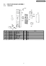
Page 27: ...E3 F800L8Y30SRP ESCUTCHEON BASE U 1 SD798S E4 F66167D00AP FLAT CABLE 1 SD798S E5 F82988N00SAP BUTTON 1 SD798S E6 F891P8N40SAP DOOR OPENING BUTTON U 1 SD798S E7 F82565X00AP DOOR OPENING LEVER 1 SD798S...

Page 28: ...AU 1 ST778S E23 F800L8Y40SRP ESCUTCHEON BASE U 1 ST778S E26 F80724W70SAP DOOR OPENING BUTTON U 1 ST778S E27 F82564W00AP DOOR OPENING LEVER 1 ST778S E28 F80375K00AP COOK BUTTON SPRING 1 E29 F630Y8Y40BR...

Page 29: ...T DU 1 SA768W E43 F80347C50HAP ESCUTCHEON BASE 1 SA768W E44 F66164W20AP FLAT CABLE 1 SA768W E45 F82987D60KAP BUTTON 1 SA768W E46 F80727C50HAP DOOR OPENING BUTTON 1 SA768W E47 F82565X00AP DOOR OPENING...

Page 30: ...P DOOR A U 1 SD798S D2 F301A8R50SAP DOOR A U 1 ST778S D3 F302K4W00AP DOOR E U 1 D4 F30215G10XN DOOR KEY SPRING 1 D5 F30854W00AP DOOR C 1 D6 F31454W00AP DOOR SCREEN A 1 D7 F31468N20HAP DOOR SCREEN B 1...

Page 31: ...RIALS Ref No Part No Part Name Description Pcs Set Remarks W1 F030A6P40AG LEAD WIRE HARNESS 1 W2 F030E6G30AP H V LEAD WIRE 1 W3 F03537B70AP LEAD WIRE HARNESS U 1 INCLUDING THERMISTOR 31 NN SD798S NN S...

Page 32: ...RPH P2 F01028Y50HRP PACKING CASE PAPER 1 SA768W RPH P3 F01044W00AP UPPER FILLER 1 SD798S ST778S P3 F01045J00AP UPPER FILLER 1 SA768W P4 F01054W00AP LOWER FILLER 1 SD798S ST778S P4 F01055J00AP LOWER F...

Page 33: ...10 DIGITAL PROGRAMMER CIRCUIT 10 1 NN SD778S 33 NN SD798S NN ST778S NN SA768W...

Page 34: ...34 NN SD798S NN ST778S NN SA768W...

Page 35: ...10 2 NN ST778S 35 NN SD798S NN ST778S NN SA768W...

Page 36: ...36 NN SD798S NN ST778S NN SA768W...

Page 37: ...10 3 NN SA768W 37 NN SD798S NN ST778S NN SA768W...

Page 38: ...38 NN SD798S NN ST778S NN SA768W...

Page 39: ...R 1 270 1 4W 5 R124 D0AE470JA155 CARBON FILM RESISTOR 1 47 1 4W 5 R229 D0AE680JA155 CARBON FILM RESISTOR 1 68 1 4W 5 RY1 AEBGJQC25F18 POWER RELAY 1 RY2 K6B1AZA00011 POWER RELAY 1 T10 G4C3AAD00006 LOW...

Page 40: ...00E DIODE 7 D10 D11 D12 D13 B0EAKT000025 DIODE 4 D25 D4EAY271A036 ZENER RESISTOR 1 270V D26 D27 D4EAY112A036 ZENER RESISTOR 2 1100V R44 R10 R11 R311 D0AE102JA155 CARBON FILM RESISTOR 4 1K 1 4W 5 R12 D...

Reviews: