background image

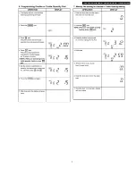
2 OPERATION PROCEDURE

5

NE-1257R/NE-1257CR / NE-1757R/NE-1757CR / NE-2157R/NE-2157CR / NE-1258

Summary of Contents for NE1257R - COMMERCIAL MICROWAVE OVEN

Page 1: ...tric Industrial Co Ltd All rights reserved Unauthorized copying and distribution is a violation of law NE 1257R NE 1257CR NE 1757R NE 1757CR NE 2157R NE 2157CR NE 1258R Commercial Microwave Oven ORDER...

Page 2: ...M NE 1257CR 12 6 SCHEMATIC DIAGRAM NE 1757R 13 7 SCHEMATIC DIAGRAM NE 1757CR 14 8 SCHEMATIC DIAGRAM NE 2157R 15 9 SCHEMATIC DIAGRAM NE 2157CR 16 10 WIRING DIAGRAM NE 1257R NE 1258R 17 11 WIRING DIAGRA...

Page 3: ...2 21 PROCEDURE FOR MEASURING MICROWAVE ENERGY LEAKAGE 33 22 TROUBLESHOOTING GUIDE 35 23 EXPLODED VIEW AND PARTS LIST 36 24 PARTS LIST 37 25 DOOR ASSEMBLY 40 26 ESCUTCHEON BASE ASSEMBLY 41 27 PACKING A...

Page 4: ...1 OUTLINE DIAGRAM 4 NE 1257R NE 1257CR NE 1757R NE 1757CR NE 2157R NE 2157CR NE 1258R...

Page 5: ...2 OPERATION PROCEDURE 5 NE 1257R NE 1257CR NE 1757R NE 1757CR NE 2157R NE 2157CR NE 1258...

Page 6: ...6 NE 1257R NE 1257CR NE 1757R NE 1757CR NE 2157R NE 2157CR NE 1258R...

Page 7: ...7 NE 1257R NE 1257CR NE 1757R NE 1757CR NE 2157R NE 2157CR NE 1258...

Page 8: ...8 NE 1257R NE 1257CR NE 1757R NE 1757CR NE 2157R NE 2157CR NE 1258R...

Page 9: ...9 NE 1257R NE 1257CR NE 1757R NE 1757CR NE 2157R NE 2157CR NE 1258...

Page 10: ...oltage selector connector on the back of the oven is set for your power supply Connecting oven to 230 volt line with 208 voltage setting is dangerous and may result in overheating of the electrical co...

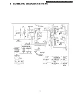
Page 11: ...4 SCHEMATIC DIAGRAM NE 1257R NE 1258R 11 NE 1257R NE 1257CR NE 1757R NE 1757CR NE 2157R NE 2157CR NE 1258...

Page 12: ...5 SCHEMATIC DIAGRAM NE 1257CR 12 NE 1257R NE 1257CR NE 1757R NE 1757CR NE 2157R NE 2157CR NE 1258R...

Page 13: ...6 SCHEMATIC DIAGRAM NE 1757R 13 NE 1257R NE 1257CR NE 1757R NE 1757CR NE 2157R NE 2157CR NE 1258...

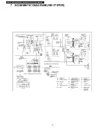
Page 14: ...7 SCHEMATIC DIAGRAM NE 1757CR 14 NE 1257R NE 1257CR NE 1757R NE 1757CR NE 2157R NE 2157CR NE 1258R...

Page 15: ...8 SCHEMATIC DIAGRAM NE 2157R 15 NE 1257R NE 1257CR NE 1757R NE 1757CR NE 2157R NE 2157CR NE 1258...

Page 16: ...9 SCHEMATIC DIAGRAM NE 2157CR 16 NE 1257R NE 1257CR NE 1757R NE 1757CR NE 2157R NE 2157CR NE 1258R...

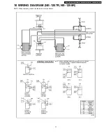
Page 17: ...10 WIRING DIAGRAM NE 1257R NE 1258R NOTE When replacing check the lead wire color as shown 17 NE 1257R NE 1257CR NE 1757R NE 1757CR NE 2157R NE 2157CR NE 1258...

Page 18: ...11 WIRING DIAGRAM NE 1257CR NOTE When replacing check the lead wire color as shown 18 NE 1257R NE 1257CR NE 1757R NE 1757CR NE 2157R NE 2157CR NE 1258R...

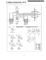
Page 19: ...12 WIRING DIAGRAM NE 1757R NOTE When replacing check the lead wire color as shown 19 NE 1257R NE 1257CR NE 1757R NE 1757CR NE 2157R NE 2157CR NE 1258...
Page 20: ...13 WIRING DIAGRAM NE 1757CR NOTE When replacing check the lead wire color as shown 20 NE 1257R NE 1257CR NE 1757R NE 1757CR NE 2157R NE 2157CR NE 1258R...

Page 21: ...14 WIRING DIAGRAM NE 2157R NOTE When replacing check the lead wire color as shown 21 NE 1257R NE 1257CR NE 1757R NE 1757CR NE 2157R NE 2157CR NE 1258...

Page 22: ...15 WIRING DIAGRAM NE 2157CR NOTE When replacing check the lead wire color as shown 22 NE 1257R NE 1257CR NE 1757R NE 1757CR NE 2157R NE 2157CR NE 1258R...

Page 23: ...cuit controls the ON OFF time of the power relay A and B contacts in order to vary the output power of the microwave oven One complete ON and OFF cycle of the power relay is 44 seconds The relation be...

Page 24: ...operated with any of these parts in imperfect condition hazardous microwave leakage might occur 17 3 Warning about the electric charge in the high voltage capacitor For about 30 seconds after the oven...

Page 25: ...ll electrical connections are tight before inserting the plug into the wall outlet 17 6 Avoid inserting nails wire etc through holes in unit during operation Never insert a wire nail or any other meta...

Page 26: ...on the high voltage capacitors 2 Remove the entire rear panel by removing screws as shown 3 Carefully place the unit on its left side H V Capacitor side 4 Remove the cover by removing 2 screws 5 Remov...

Page 27: ...ve the power supply P C B together with its mounting bracket by first removing the 2 bracket holding screws 3 The power supply P C B can be separated from mounting bracket by removing the 2 L V T hold...

Page 28: ...clockwise to unhook the tabs and pull off 18 5 Replacement of floor shelf and lower antenna 1 To remove the floor shelf insert a screwdriver through the small opening on the left side of the oven cav...

Page 29: ...E by carefully freeing catch hooks 5 Remove door key door key lever door key spring and handle pins from door E 6 Assemble the door by taking the above steps in a reverse order Replacement 1 When moun...

Page 30: ...he circuit by disconnecting the leads 2 With the ohmmeter set on the highest resistance scale measure the resistance across the diode terminals Reverse the meter leads and again observe the resistance...

Page 31: ...al protector will operate at 257 F 125 C The device is connected to the DPC on touch control models When the thermal protector exceeds its temperature it will turn off the power to oven cavity and dis...

Page 32: ...nitor circuit and all latch switches again 20 2 Measurement of microwave output The power output of the magnetron can be determined by performing IEC standard test procedures However due to the comple...

Page 33: ...llating measure the leakage by holding the probe perpendicular to the surface being measured 1 Measurement with the outer pane removed Whenever you replace the magnetron measure for radiation leakage...

Page 34: ...34 NE 1257R NE 1257CR NE 1757R NE 1757CR NE 2157R NE 2157CR NE 1258R...

Page 35: ...22 TROUBLESHOOTING GUIDE 35 NE 1257R NE 1257CR NE 1757R NE 1757CR NE 2157R NE 2157CR NE 1258...

Page 36: ...23 EXPLODED VIEW AND PARTS LIST 36 NE 1257R NE 1257CR NE 1757R NE 1757CR NE 2157R NE 2157CR NE 1258R...

Page 37: ...ANE0911000MG CUSHION RUBBER B 1 13 ANE000Z000AA CUSHION RUBBER C 10 13 ANE000Z000AA CUSHION RUBBER C 10 13 ANE000Z000AA CUSHION RUBBER C 10 13 ANE000Z000AA CUSHION RUBBER C 10 13 ANE000Z000AA CUSHION...

Page 38: ...UTOUT 2 57 ANE61458U0AP THERMAL CUTOUT 2 58 A605S3650CP PC BOARD H U 1 NE 1257CR 58 A605S3660CP PC BOARD H U 1 NE 1757CR NE 2157CR 59 ANE60708U0BP INSULATION SHEET A 1 60 A60713310BP INSULATION SHEET...

Page 39: ...CAPACITOR BRACKET AC CORD MOTOR COVER BASE METAL ETC 106 XYD4 EE12F SCREW 11 4X12 FOR DIODE CAPACITOR BRACKET AC CORD MOTOR COVER BASE METAL ETC 106 XYD4 EE12F SCREW 11 4X12 FOR DIODE CAPACITOR BRACKE...

Page 40: ...A3018 3850 DOOR KEY A 1 D8 A3019 3850 DOOR KEY B 1 D9 ANE30218U0AP DOOR KEY SPRING 1 D10 ANE30562Q0AP HANDLE PIN 2 D10 ANE30562Q0AP HANDLE PIN 2 D11 A30703170GP HANDLE PEICE A 1 D12 ANE3081P60AP DOOR...

Page 41: ...TCHEON SHEET 1 E2 A603M3310GP PC BOARD B U 1 E3 A64793310QP MEMBRANE SWITCH 1 E4 A6590 3280 FLAT CABLE 1 E5 ANE80018U0AP ESCUTCHEON A 1 E6 ANE80028U0AP ESCUTCHEON B 1 E7 ANE80068U0AP ESCUTCHEON D 1 E8...

Page 42: ...A01023990AP PACKING CASE PAPER 1 NE 1258R P3 A01023970CP PACKING CASE PAPER 1 NE 1757CR P3 A01023970AP PACKING CASE PAPER 1 NE 1757R P3 A01023980AP PACKING CASE PAPER 1 NE 2157R P3 A01023980CP PACKING...

Page 43: ...A3980CP LEAD WIRE HARNESS 1 NE 2157CR W2 A030H3960AP LEAD WIRE HARNESS 1 W3 A50966520UP FERRITE CORE 2 NE 1257CR NE 1757CR NE 2157CR W3 A50966520UP FERRITE CORE 2 NE 1257CR NE 1757CR NE 2157CR W3 A509...

Page 44: ...POWER RELAY 1 G5B 1 E 18VDC RY3 4 5 AEG5J1EM18B POWER RELAY 5 NE 1757CR NE 1757R NE 2157R NE 2157CR G5J 1 TP M ER18 RY3 4 6 7 AEG5J1EM18B POWER RELAY 4 NE 1257CR NE 1257R NE 1258R G5J 1 TP M ER18 T100...

Page 45: ...Ref No Part No Part Name Description Pcs Set Remarks CN250 AEEMHLIM21S CONNECTOR 1 21PIN DISP25 0 A64563080AP FLOURESCENT TUBE 1 FV443 ANE82848U2AP SPACER 1 45 NE 1257R NE 1257CR NE 1757R NE 1757CR NE...

Page 46: ...32 DIGITAL PROGRAMMER CIRCUIT SCHEMATIC DIAGRAM 46 NE 1257R NE 1257CR NE 1757R NE 1757CR NE 2157R NE 2157CR NE 1258R...

Page 47: ...47 NE 1257R NE 1257CR NE 1757R NE 1757CR NE 2157R NE 2157CR NE 1258...

Page 48: ...B S Q1 2SD2012 TRANSISTOR SI 2W 1 2SD2012 Q2 3 2SA720RRTA TRANSISTOR SI 400MW 2 Q4 UN4115 TA TRANSISTOR SI 300MW 1 UN4115 Q7 UN421F TA TRANSISTOR SI 1 UN421F Q8 9 11 SD1991AQSTA TRANSISTOR SI 3 2SD199...

Reviews: