19
6.3.
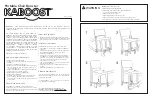
Bottom plate
1. The bottom plate can be removed when its four screws
are lossened.
6.4.
Connector(Lower)
1. Hold the part under the motor shaft by means of a
screws-driver, then turn the connector (lower) clockwise.
The connector (lower) can be removed.
• The connector (lower) can be relatively easily removed
by means of hitting its projecting section clockwise with
use of a screwdriver grip in a forceful manner.
6.5.
Cord U
1. Pull out while the faston terminal with the part of the Cord
U.
Summary of Contents for MX-151SG2WTB
Page 2: ...2 1 Safety Precautions ...
Page 4: ...4 3 Location of Controls and Components ...
Page 5: ...5 ...
Page 6: ...6 4 Operating Instructions 4 1 How to Use Blender ...
Page 7: ...7 ...
Page 8: ...8 ...
Page 9: ...9 4 2 How to Use Dry Mill ...
Page 10: ...10 ...
Page 11: ...11 ...
Page 12: ...12 4 3 Safety ...
Page 13: ...13 ...
Page 14: ...14 4 4 How to Clean ...
Page 15: ...15 ...
Page 22: ...22 6 9 Safety unit 1 Safety unit can be removed when its two screws is loss ened ...
Page 23: ...23 7 Wiring Connection Diagram 7 1 Schematic diagram ...
Page 24: ...24 7 2 Basic wiring diagram ...
Page 25: ...25 8 Exploded View and Replacement Parts List 8 1 PARTS LOCATION ...
Page 27: ...27 8 3 PACKING INSTRUCTION ...