
Interf
ace connectors
AXJ4
NOTES
1. Use of a cover is recommended
when using this device in order to
prevent scraps, dust, dirt, etc., from
getting inside of the receptacle.
2. PC board design
Please refer to the recommended PC
board pattern to ensure the strength of
soldered portion of terminals.
3. Soldering
1) Manual soldering
• Please set up temperature and applied
time of soldering iron as indicated in
specification sheet.
• Please use soldering iron after
confirming removal of dispersed solder
flux on the contact surface by use of
magnifying glass after each soldering.
• Please properly clean soldeing iron.
2) Reflow soldering
• Screen printing is recommended for
cream solder printing.
• Screen thickness of 0.15mm is
recommended for cream solder printing.
• When applying different thickness of
screen, please consult us.
• Depending upon size of connector, self
alignments may not be expected.
Please pay attention to align terminals
and soldered pads.
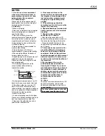
• The following diagram shows the
recommended reflow soldering
temperature profile.
• The temperature measured on the PC
board surface near connector terminals.
• After reflow soldering, in case of PC
board surface the reverse side using
reflow soldering, for example an adhesive
and so on connector of fixed disposition.
3) Rework of soldering portion
• Rework is one time.
• In case of soldering rework of bridges.
Please use a flat-head soldering iron and
don’t use supplementary solder flux.
• Please use the soldering iron under
specification’s temperature
4. Since excessive force on the
terminals will cause deformation and
the integrity of the soldering will be
lost during reflow soldering, avoid
dropping or rough handling of the
product.
5. PC board warpage should be
controlled less than 0.03mm to entire
length of the connector.
6. Repeated bending of terminals and
holding parts can result in terminals
breaking.
7. Regarding after soldering
connectors on PC boards
• After mounting connectors on PC
boards, do not apply excessive loads to
the connector by piling up the boards.
• Please do not add the force to the
connector during assembled connector
on PC board.
8. This connector has metal shell for
preventing EMI, when designing an
enclosure the followings should be
considered. Guide for plug entrance
should be arranged in order to prevent
distorted insertions. Provide a cover
to reinforce the metal shell portions of
the receptacle.
9. We recommend the use of a
purified-water-based solution for
cleaning the PC board. If you use an
alcohol-based solution, the surface of
the molded part may be whitened. In
addition, please carefully monitor the
contamination degree of the solution
to prevent the solution from re-
contaminating the connector
contacts.
10. Others
To prevent insulation deterioration of PC
board after soldering, please avoid
adhesion coating agent to terminals in
case of coating.
60 to 120 second
Pre-heating
Time
Temperature
Maximum temperature
200
°
C
150 to 175
°
C
Max. 260
°
C
Max. 70 sec
For other details, please verify with
the product specification sheets.
http://www.mew.co.jp/ac/e/
Matsushita Electric Works, Ltd.


