


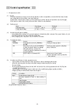


Connections on PCB
The following shows connections of connector on Main PCB.
Connector
Connects to
Usage
CN1
Emulator
To version up firmware
CN2
#1~#6: MTR-480/MTR-L03 (Option)
To connect with MTR-480/MTR-L03.
CN3
Remote alarm terminal
#1: COM
#2: N.O.
#3: N.C.
Remote alarm contact outputs.
CN4
#1~#2
Jumper
To upgrade firmware version
CN5
#1,#7:USB PCB
#8,#9:Door switch
To connect with LCD PCB
To detect door open and shut
CN6
#1~#2
:
Temp. sensor
To control chamber temperature
CN7
#1~#2
:
Cascade sensor
#3~#4
:
Filter sensor
To detect temperature of cascade
To detect temperature of filter
CN8
#1~#2
:
AT sensor
To detect ambient temperature
CN9
#1~#4:Unused
CN11
#1,#2:Main battery switch
To supply power during power failure
CN12
#1,#3:Battery switch
To supply power during power failure
CN14
#1~#6:Back-up battery charging PCB
To control
battery charging
CN15
#1~#3:Inverter L
#3~#6:Inverter H
To control inverter L
To control inverter H
CN16
#1~#4:Unused
CN17
#1,#2:
Auto air intake port (AIP) heater
To control AIP
heater
CN101
#1,#4:Recorder, Power switch
To supply power to PCB
CN103
#1
、
#3
:
Fan motor condenser
To control condensing fan motor
-11-
Summary of Contents for MDF-DU502VH
Page 8: ...Dimension MDF DU502VH 5 ...
Page 9: ...MDF DU702VH 6 ...
Page 17: ...Wiring Diagram 14 ...
Page 18: ...main Circuit Diagram 15 ...
Page 19: ...power 16 ...
Page 20: ...USB 17 ...
Page 73: ...WIRING YG Y Y GR B G W W W Y G R BL Y W R R BL R OR B BL R OR B Y W Y G Y G R BL 70 ...


