– A-2 –
Panasonic Corporation Electromechanical Control Business Division
industrial.panasonic.com/ac/e/
©
Panasonic Corporation 2018
AQCTB02E 201806-E
– A-3 –
Panasonic Corporation Electromechanical Control Business Division
industrial.panasonic.com/ac/e/
©
Panasonic Corporation 2018
AQCTB02E 201806-E
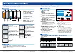
Configuration and contents of catalog
Product description / Conversion Table
Information contained in the catalog
Induction motor
Reversible motor
3-phase motor
Electromagnetic
brake motor
Variable speed
induction motor
Variable speed
reversible motor
Variable speed
electromagnetic brake
single-phase motor
Variable speed
unit motor
C&B motor
2-pole round
shaft
motor
Gear head
Gear head -inch
(U.S.A.)
Induction motor (leadwire)
– B-12 –
!"
– B-13 –
!"
*
Motor
*
Connection diagram
B-58
B-448
B-449
B-61
ø4.3(ø0.17) hole
Faston 187 tab
(t0.5 mm, t0.02 inch)
2–ø2.5(ø0.10) hole
1.5(0.06)
6.2 (0.24)
10(0.39)
MAX
H
D
W
T
L
Indication
Capacitor
(W4)
W3
(W2)
W1
ø4(ø0.16)
(61(2.40))
12
(0.47)
17
(0.67)
Unit: mm (inch)
Capacitor cap
Helical
gear
Module
0.5
Number
of teeth
6
Mass
0.56
k
g
1.23
lb
l
78(3.07)
65(2.56)
MAX
ø65(
ø2.56)
13(0.51)
7(0.28)
2.5(0.10)
ø54h7
(ø
2.13h7)
O-ring
60 mm sq.
(2.36 inch sq.)
4– ø4.5(ø0.18)
ø70
(ø2.76)
CW
CCW
4 motor leadwires 300±30 mm (11.8±1.18 inch)
AWG20
M61X3G4L
39.5
(1.56)
37.5
(1.48)
17
(0.67)
15
(0.59)
W1
W2
W3
W4
M61X3G4L
39.5
(1.56)
16
(0.63)
26.5
(1.04)
30.5
(1.20)
4
(0.16)
M0PC2M20
M0PC3917
Model number
of motor
Capacitor cap
(option)
L
W
D
H
T
Model number of capacitor
(attachment)
Black
Gray
Primary
Auxiliary
Brown
White
Black
Brown
Primary
Auxiliary
Gray
White
CW
(clockwise)
Capacitor Cr
CCW
(counterclockwise)
Capacitor Cr
Motor model No.
Rating
Size
Number
of pole
(P)
Output
(W)
Voltage
(V)
Frequency
(Hz)
Rating
(min) Input
(W)
Current
(A)
Torque
N·m
(oz-in)
Starting torque
N·m
(oz-in)
Capacitor
(F)
(rated voltage)
Starting
current
(A)
Speed
(r/min)
M61X3G4L
2.0
(200 V)
0.031
(4.4)
0.031
(4.4)
0.022
(3.1)
0.018
(2.5)
60
mm
sq.
4
3
100
50
60
15
15
0.15
0.15
1250
1575
0.18
0.19
Cont.
MX6G10XB
Reverse to motor rotational direction
2.45 2.45 2.45 2.45 2.45 2.45 2.45
2.45
2.45
600
2.5
3
500
3
3.6
250
6
7.2
300
5
6
360
4.2
5
200
7.5
9
750
2
2.4
900
1.7
2
1000
1.5
1.8
2.45
1200
1.3
1.5
2.45
1500
1
1.2
2.45
1800
0.8
1
MX6G BA
MX6G B
MX6G MA
MX6G M
3
500
600
3.6
416.7
500
5
300
360
6
250
300
7.5
200
240
9
166.7
200
10
150
180
12.5
120
144
15
100
120
18
83.3
100
20
75
90
25
60
72
30
50
60
36
41.7
50
50
30
36
60
25
30
75
20
24
90
16.7
20
100
15
18
120
12.5
15
150
10
12
180
8.3
10
0.048
(0.42)
0.058
(0.51)
0.079
(0.70)
0.095
(0.84)
0.12
(1.1)
0.14
(1.2)
0.16
(1.4)
0.20
(1.8)
0.24
(2.1)
0.28
(2.5)
0.31
(2.7)
0.38
(3.4)
0.46
(4.1)
0.55
(4.9)
0.76
(6.7)
0.92
(8.1)
1.08
(9.6)
1.27
(11.2)
1.47
(13.0)
1.76
(15.6)
2.16
(19.1)
2.45
(21.7)
0.040
(0.35)
0.048
(0.42)
0.067
(0.59)
0.079
(0.86)
0.098
(0.87)
0.12
(1.1)
0.13
(1.2)
0.17
(1.5)
0.20
(1.8)
0.24
(2.1)
0.25
(2.2)
0.32
(2.8)
0.38
(3.4)
0.46
(4.1)
0.64
(5.7)
0.76
(6.7)
0.90
(8.0)
1.08
(9.6)
1.27
(11.2)
1.47
(13.0)
1.76
(15.6)
2.16
(19.1)
Same as motor rotational direction
Reverse to motor rotational direction
Unit of permissible torque: upper
/ lower
MX6G3BA
MX6G180B
(ball bearing)
MX6G3MA
MX6G180M
(metal bearing)
Same as motor
rotational direction
ball
(
bearing
)
metal
(
bearing
)
0
0
1800
60 Hz
50 Hz
0.05
0.04
0.03
0.02
0.01
1500
1000
500
(N·m)
Speed (r/min)
Torque
(oz-in)
2
4
6
M61X3G4L
60
mm
(
2.36
inch
)
3
W
*
□
□
26(1.02)[33(1.30)]
32(1.26)
ø8h7
(ø
0.31h7)
ø25
(ø
0.98)
7(0.28)
10(0.39)
6(0.24)
60 mm sq.
(2.36 inch sq.)
ø70(
ø2.76
)
4–ø4.5(ø0.18)
12(0.47)
Gear head
MX6G
□
BA
g
MX6G
□
B
g
MX6G
□
MA
g
MX6G
□
M
g
Index
• Each series is color coded.
Motors
Controls
• Classification is made in terms of function.
Size and output
• Indicates the size and output shown on the page.
Footer
• Indicates the page(s) on which related products
and information are found.
• Product information ( to )
• The facing page contains product specifications.
Specification
• Defines major requirements such as voltage,
current and torque.
• Description is basically on pinion shaft type but
almost equally applicable to round shaft.
Permissible load torque with gear head
directly connected
• Specifies the allowable load torque with gear
head directly connected.
Permissible load torque with
decimal gear head used
• Specifies the allowable load torque when the
decimal gear head is used.
Wiring diagram
• Represents typical wiring for the product.
Speed-torque curve
• Represents typical speed-torque curve of the
product.
Outline drawing
• Shows dimensions of the motor (gear head).
• Dimensions of motor-gear head combination and
round shaft type are shown on different pages.
See the footer.
• Fit tolerance symbol (JIS) is used in dimensions
of motor “Faucet face” and “gear head” output
shaft. For further information, see page A-33.
Options/index
Controls
Motors
Information
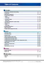
The catalog is divided into the following sections.
Configuration
Information
• Product Type Contents
List of all product families introduced
in this catalog.
A-28
• Terminology
Description of terms used
in this catalog.
A-32
• Motor selection
Guidance to select the most
suitable motor for the application.
A-48
• Safety standard
approved motor
Outline of product safety standards
referenced in this catalog.
A-59
• Product list
List of motors and gear heads
A-4
Front page
Product description
• Handling instructions
Description of special precautions
and handling techniques that must
be implemented to assure product
performance.
A-35
• Selection by keywords
Objective product can be found by
using keywords (function, specification).
A-24
• Information
Information on product selection, terms
used in this catalog, handling
precautions and safety standards.
• Product description
<Motors>
List of motors and gear heads
<Controls>
Control related products
• Options & index
List of options. Index sorted by parts
number. (Alphabetical order)
A-2 to A-62
B-1 to B-456
C-1 to C-36
D-1 to D-16
The product is briefly described by using the following information and data.
• Overview, system block diagram, part No. description, product-specific information
• Model list
• Product information for each model
Product outline
To convert top row values to left column values(or vice versa),mulitply by the value in the table.
(X = Y x multiply unit)
Conversion Table
Description of product
A
C
B
D
D
E
F
G
H
I
I
D
E
F
G
H
I
B
C
A
N
•
m
oz-in
lb-in
N
•
m
1
7.061541 x 10
–3
1.12985 x 10
3
oz-in
141.6121
1
16
lb-in
8.850759
0.0625
1
• Torque
mm
cm
m
in
mm
1
10
1000
25.4
cm
0.1
1
100
2.54
m
0.001
0.01
1
0.0254
in
0.0393701
0.393701
39.3701
1
• Length
g
kg
oz
lb
g
1
1000
28.3495
453.592
kg
0.001
1
0.0283495
0.453592
oz
0.035274
35.274
1
16
lb
0.00220462
2.20462
0.0625
1
• Weight
kg-cm
2
oz-in
2
lb-in
2
kg-cm
2
1
0.182899
2.9263
oz-in
2
5.46745
1
16
lb-in
2
0.341718
0.0625
1
• Inertia
X
Y
X
Y
X
Y
X
Y


