


46
10.3. Details of Electrical Adjustment
10.3.1.
How to execute the Electrical Adjustment
It is not necessary to connect the camera to a PC to perform adjustments.
"Flag reset operation" and "Initial setting operation" are required when carrying out the alignment, follow the procedure below.
10.3.1.1. Startup Electrical Adjustment mode
1. Release the initial settings.
2. Insert a recordable SD card.
(Without a SD card, the automatic adjustment can not
executed.)
3. Procedure to set the camera into adjustment mode:
a. Set the mode dial to Normal picture mode.
b. Turn the Power SW off.
c. Turn the Power SW on pressing DISPLAY and Menu
simultaneously.
LCD monitor displays "SERVICE MODE". (Refer to
Fig.F3-1)
Fig. 3-1
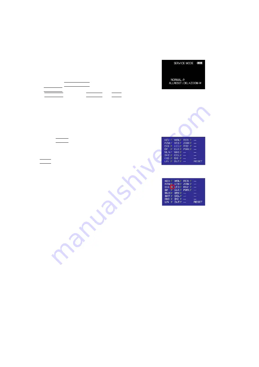
10.3.1.2. Status Adjustment Flag Setting
Reset (Not yet adjusted) the status flag condition.
1. After pressing the Display button, the LCD monitor dis-
plays the Flag status screen (Refer to Fig.3-2.)
2. Select item by pressing the cross keys. (Gray cursor is
moved accordingly.)
3. Press the Delete button.
Note:
The selected item's flag has been changed from
"F (green)" to "0 (yellow)".
*(Refer to Fig. 3-3)
*Flag conditions:
F (green)
means that the alignment has been completed and the
status flag condition is set. In this case, the flag condition
should be reset, if you try to carry out the automatic align-
ment.
0 (yellow)
means that the alignment has been not "completed"and
the status flag condition is "reset". In this case, automatic
alignment is available.
Fig. 3-2
Fig. 3-3
<Example: OIS flag is reset.>
• In case of setting the status flag into set condition again without completion of the alignment, the status flag should be SET by
using PC, or UNDO by using ROM BACKUP function.
Summary of Contents for Lumix DMC-TS10GH
Page 15: ...15 4 Specifications ...
Page 17: ...17 ...
Page 18: ...18 ...
Page 19: ...19 ...
Page 20: ...20 ...
Page 21: ...21 ...
Page 22: ...22 5 Location of Controls and Components ...
Page 23: ...23 ...
Page 37: ...37 9 Disassembly and Assembly Instructions 9 1 Disassembly Flow Chart 9 2 P C B Location ...
Page 39: ...39 9 3 2 Removal of Rear Case Unit Fig D3 Fig D4 Fig D5 ...
Page 41: ...41 Fig D8 9 3 5 Removal of Battery Frame Unit Fig D9 Fig D10 ...
Page 42: ...42 9 3 6 Removal of Flash Top P C B Fig D11 Fig D12 ...
Page 43: ...43 9 3 7 Removal of Sub Ope P C B Fig D13 9 3 8 Removal of LCD Unit Fig D14 ...


