


16
Mode switching
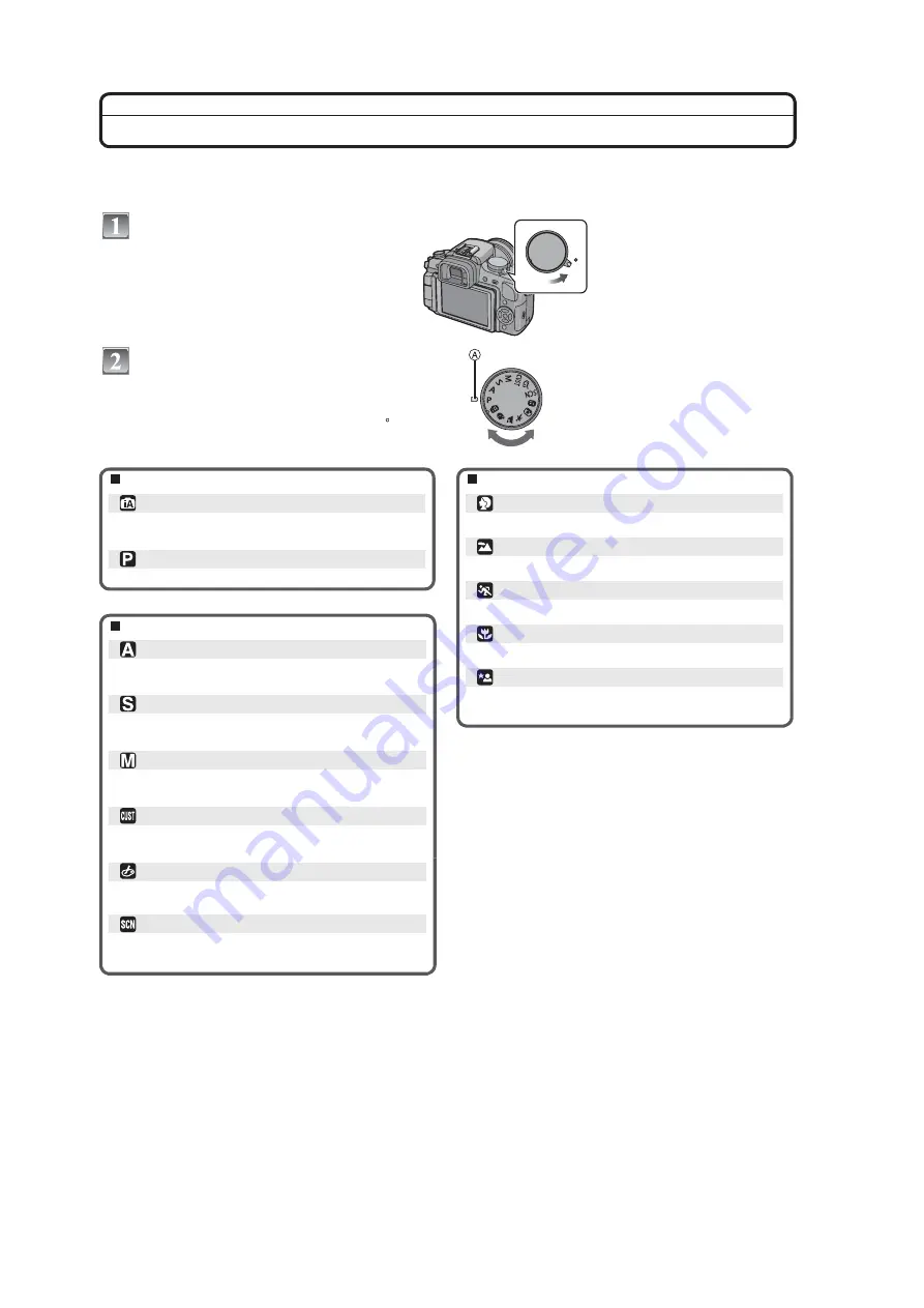
Selecting the [REC] Mode
When the [REC] mode is selected, the camera can be set to the Intelligent auto mode in which the optimal settings are
established in line with the subject to be recorded and the recording conditions, or to the scene mode which enables
you to take pictures that match the scene being recorded.
Turn the camera on.
Switching the mode by rotating the mode
dial.
Align a desired mode with part
.
Rotate the mode dial slowly and surely to adjust
to each mode. (
The mode dial rotates 360
Q
)
Basic
Intelligent auto mode
The subjects are recorded using settings automatically
Program AE mode
The subjects are recorded using your own settings.
ON
OFF
Advanced
Advanced scene mode
Aperture-priority AE mode
The shutter speed is automatically determined by the
Shutter-priority AE mode
The aperture value is automatically determined by the
Manual exposure mode
The exposure is adjusted by the aperture value and the
shutter speed which are manually adjusted.
Custom mode
Use this mode to take pictures with previously registered
settings.
My color mode
Easily check the color of light, brightness, and vividness
of color when the picture is taken.
Scene mode
This allows you to take pictures that match the scene
being recorded.
Portrait mode
Use this mode to take pictures of people.
Scenery mode
Use this mode to take pictures of scenery.
Sports mode
Use this mode to take pictures of sporting events, etc.
Close-up mode
Use this mode to take picture of close-by subject.
Night portrait mode
Use this mode to take pictures of night scenes and
people with night time scenery.
selected by the camera.
aperture value you set.
shutter speed you set.
Summary of Contents for Lumix DMC-G1KPP
Page 13: ...13 4 Specifications ...
Page 36: ...36 7 Troubleshooting Guide ...
Page 37: ...37 ...
Page 38: ...38 ...
Page 42: ...42 9 Disassembly and Assembly Instructions 9 1 Disassembly Flow Chart 9 2 PCB Location ...
Page 44: ...44 9 3 1 Removal of the Rear Case Unit Fig D1 Fig D2 ...
Page 45: ...45 9 3 2 Removal of the Top Case Unit Fig D3 9 3 3 Removal of the LVF Unit Fig D4 ...
Page 46: ...46 9 3 4 Removal of the Main P C B Fig D5 9 3 5 Removal of the Front Case Unit Fig D6 ...
Page 50: ...50 Fig D15 9 3 12 Removal of the LCD TFT Unit Fig D16 ...
Page 52: ...52 ...
Page 55: ...55 11 Maintenance ...
Page 56: ...56 ...


