23
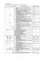
8.3.
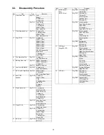
Disassembly Procedure
No.
Item
Fig
Removal
1
Rear Case Unit
(Fig. D1)
Card
Battery
3 Screws (A)
2 Screws (B)
(Fig. D2)
Shoe Spring
2 Screws (C)
1 Locking tab
FP9003 (Flex)
Rear Case Unit
2
Rear Operation Unit
(Fig. D3)
2 Screws (D)
2 Hooking parts
FP9007 (Flex)
Rear Operation Unit
3
Main P.C.B.
(Fig. D4)
1 Screw (E)
FP9001 (Flex)
FP9002 (Flex)
FP9004 (Flex)
FP9005 (Flex)
FP9006 (Flex)
FP9010 (Flex)
PS9001 (Connector)
Main P.C.B.
1 Hooking part
Jack Holder
4
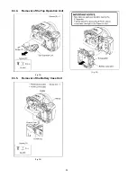
Top Operation Unit
(Fig. D5)
1 Screw (F)
Top Operation Unit
5
Battery Case Unit
(Fig. D6)
P8003 (Connector)
P8004 (Connector)
1 Screw (G)
(Fig. D7)
Battery Case Unit
6
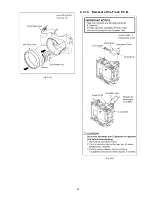
Lens Unit (W/MOS)
(Fig. D8)
4 Screws (H)
Lens Unit (W/MOS)
7
EVF Unit & Flash Parts (Fig. D9)
FP9302 (Flex)
2 Convexes
EVF Unit & Flash Parts
8
Sub P.C.B.
Speaker
(Fig. D10) 1 Screw (I)
FP9301 (Flex)
1 Rib
2 Hooking parts
Sub P.C.B.
2 Solders
Speaker
9
Side Switch Unit
(Fig. D11) 1 Locking tab
Side Frame (R)
Strap Holder (R)
1 Screw (J)
2 Locking tabs
Front Heat Sink
3 Screws (K)
(Fig. D12) Lens Ring Front
2 Convexes
Side Switch Unit
10
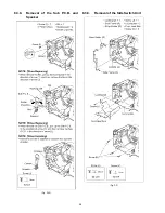
Flash P.C.B.
(Fig. D13) 3 Locking tabs
Condensor Cover
(Fig. D14) 2 Screws (L)
2 Locking tabs
FP8001 (Flex)
Switch Unit
1 Hooking part
Flash P.C.B.
11
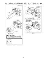
EVF Unit
(Fig. D15) 2 Locking tabs
EVF Unit
12
Hot Shoe Unit
Flash
Mic FPC Unit
(Fig. D16) 1 Hooking part
1 Screw (M)
(Fig. D17) 2 Screws (N)
1 Screw (O)
2 Locking tabs
Hot Shoe Unit
2 Screws (P)
(Fig. D18) 4 Locking tabs
Flash Case Top Unit
Flash Shaft
2 Convexes
Flash & Mic FPC Unit
(Fig. D19) 2 Locking tabs
Flash Link Cover
5 Ribs
1 Positioning Pin
2 Locking tabs
Flash
(Fig. D20) Mic Damper
Mic FPC Unit
Mic Cushion
13
LCD Parts
Hinge SW FPC
(Fig. D21) 2 Screws (Q)
2 Locking tabs
Hinge Arm Cover Top
Hinge Arm Cover Bottom
2 Screws (R)
Hinge Plate
(Fig. D22) Connector (A)
3 Ribs
LCD Parts
1 Screw (S)
1 Locking tab
Rear Earth Plate B
(Fig. D23) 2 Hinge SW Tapes
Hinge SW FPC
14
LCD Unit
(Fig. D24) 2 Screws (T)
2 Screws (U)
6 Locking tabs
LCD Case (Bottom)
(Fig. D25) Connector (B)
LCD Hinge Unit
LCD Case (Top)
LCD Unit
No.
Item
Fig
Removal
Summary of Contents for Lumix DMC-FZ200P
Page 15: ...15...
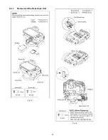
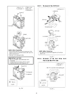
Page 24: ...24 8 3 1 Removal of the Rear Case Unit Fig D1 Fig D2...
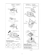
Page 25: ...25 8 3 2 Removal of the Rear Operation Unit Fig D3 8 3 3 Removal of the Main P C B Fig D4...
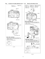
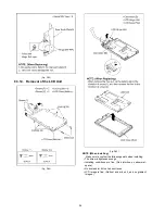
Page 29: ...29 Fig D12 8 3 10 Removal of the Flash P C B Fig D13...
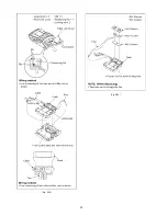
Page 31: ...31 Fig D17 Fig D18...
Page 32: ...32 Fig D19 Fig D20...
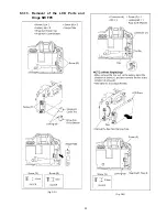
Page 33: ...33 8 3 13 Removal of the LCD Parts and Hinge SW FPC Fig D21 Fig D22...
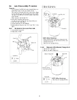
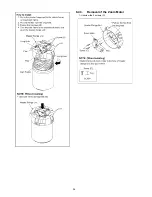
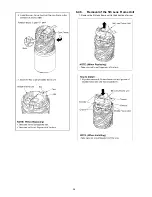
Page 36: ...36 8 4 3 Removal of the Zoom Motor 1 Unscrew the 2 screws C...
Page 43: ...43...
Page 49: ...49...
Page 58: ...Model No DMC FZ200 Schematic Diagram Note...
Page 59: ...Model No DMC FZ200 Parts List Note...
Page 60: ...Model No DMC FZ200 Power P Main P C B...
Page 61: ...Model No DMC FZ200 Jack J Main P C B...
Page 62: ...Model No DMC FZ200 EXT MIC EM Main P C B...
Page 63: ...Model No DMC FZ200 Digital D Main P C B...
Page 64: ...Model No DMC FZ200 SD Card SD Main P C B...
Page 65: ...Model No DMC FZ200 Gyro GY Main P C B...
Page 66: ...Model No DMC FZ200 Hot Shoe HS Main P C B...
Page 67: ...Model No DMC FZ200 Main Connection MC Main P C B...
Page 68: ...Model No DMC FZ200 System Driver SY Main P C B...
Page 69: ...Model No DMC FZ200 Flash Flash P C B...
Page 70: ...Model No DMC FZ200 Sub Sub P C B...
Page 71: ...Model No DMC FZ200 Lens Flex Lens Flex P C B...
Page 72: ...Model No DMC FZ200 Main P C B Component Side...
Page 73: ...Model No DMC FZ200 Main P C B Foil Side...
Page 74: ...Model No DMC FZ200 Flash P C B Component Side...
Page 75: ...Model No DMC FZ200 Flash P C B Foil Side...
Page 76: ...Model No DMC FZ200 Sub P C B Component Side...
Page 77: ...Model No DMC FZ200 Sub P C B Foil Side...
Page 78: ...Model No DMC FZ200 Lens Flex P C B...
Page 86: ...Model No DMC FZ200 Frame and Casing Section...
Page 87: ...Model No DMC FZ200 Camera Lens Section...
Page 88: ...Model No DMC FZ200 Packing Parts and Accessories Section...

