


21
8.3.
Disassembly Procedure
8.3.1.
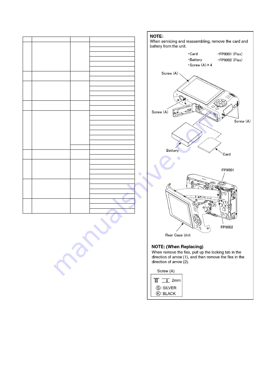
Removal of the Rear Case Unit
(Fig. D1)
No.
Item
Fig
Removal
1
Rear Case Unit
Card
Battery
4 Screws (A)
FP9001(Flex)
FP9002(Flex)
Rear Case Unit
2
LCD Unit
2 Locking tabs
LCD Unit
3
Front Case Unit
5 Screws (B)
3 Screws (C)
Tripod Fixing Plate
Front Case Unit
4
Top Operation Unit
PS8001(Connector)
Top Operation Unit
5
Flash Top P.C.B.
2 Screws (D)
6 Locking tabs
Top Operation Unit
Power knob
P8001(Connector)
Flash Cover
Flash Top P.C.B.
Discharge the capacitor
6
Main P.C.B.
PP9001(Connector)
Main P.C.B.
7
Lens Unit
FP9801(Flex)
FP9802(Flex)
1 Locking tab
Lens Unit
8
Sub P.C.B.
1 Screw (E)
1 Locking tab
PCB Spacer
Sub P.C.B.
9
Battery Case
(Fig. D10) Frame
3 Locking tabs
Battery Case
Summary of Contents for Lumix DMC-FX3EB
Page 8: ...8 NOTE Above caution is applicable for a battery pack which is for DMC FX3 series as well ...
Page 12: ...12 4 Specifications ...
Page 13: ...13 5 Location of Controls and Components ...
Page 20: ...20 8 Disassembly and Assembly Instructions 8 1 Disassembly Flow Chart 8 2 PCB Location ...
Page 30: ...30 ...


