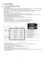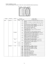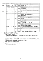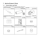
24
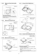
8.3.8.
Removal of the AF Assist LED
P.C.B.
(Fig. D11)
8.3.9.
Removal of the Sub P.C.B.
(Fig. D12)
8.3.10. Removal of the Jack Door
(Fig. D13)
8.3.11. Removal of the Battery Case
(Fig. D14)
(Fig. D15)
8.3.12. Removal of the Battery Door Unit
(Fig. D16)
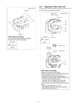
NOTE: (When Assembling)
Be sure to confirm the following points when assembling.
• The Screw is tightened enough.
• Assembling conditions are fine. (No distortion, no illegal-
space.)
• No dust and/or dirt on every Lens surfaces.
• LCD image is fine. (No dust and dirt on it, and no gradient
images.)
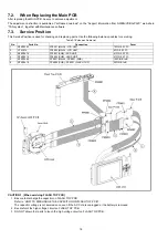
Summary of Contents for Lumix DMC-FX33E
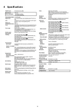
Page 12: ...12 4 Specifications ...
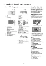
Page 13: ...13 5 Location of Controls and Components ...
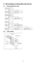
Page 19: ...19 8 Disassembly and Assembly Instructions 8 1 Disassembly Flow Chart 8 2 PCB Location ...
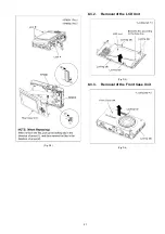
Page 21: ...21 Fig D2 8 3 2 Removal of the LCD Unit Fig D3 8 3 3 Removal of the Front Case Unit Fig D4 ...
Page 23: ...23 Fig D8 8 3 6 Removal of the Main P C B Fig D9 8 3 7 Removal of the Lens Unit Fig D10 ...
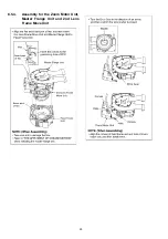
Page 28: ...28 8 5 4 Assembly for the Zoom Motor Unit Master Frange Unit and 2nd Lens Frame Move Unit ...

