24
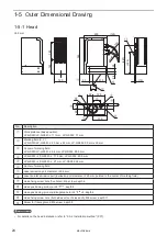
1-5 Outer Dimensional Drawing
1-5-1 Head
Unit: mm
120
q
365
183
143
120
60
y
w
e
o
1@
1#
1)
1!
i
t
u
40
60
r
(222
)
(287)
(15)
(125)
230
37
R100
R100
25
35
131.5
139
No.
Description
q
Work distance (base position):
LP-GS051/LP-GS051-L: 111 mm, LP-GS052: 71 mm
w
Marking field (X, Y):
LP-GS051/LP-GS051-L: 55 mm x 55 mm, LP-GS052: 30 mm x 30 mm
e
Center of marking field:
LP-GS051/LP-GS051-L: 54 mm, LP-GS052: 50.5 mm
r
LP-GS051 / LP-GS051-L: 77.5 mm, LP-GS052: 69.5 mm
t
LP-GS051 / LP-GS051-L: 27 mm, LP-GS052: 24 mm
y
Center of marking field
u
Laser emission port diameter:
φ
94 mm
i
Laser pointer emission port (Emission port diameter:
φ
20 mm, pointed to the center of marking field)
o
Head fixing screw hole (five holes): M6 screw, depth 6
1)
Head positioning pin hole:
φ
4
+0.012
0
, depth 5
1!
Head positioning pin hole: Elongated hole
φ
4
+0.05
0
×5, depth 5
1@
Head fixing screw hole (both sides at four holes each): M6 screw, depth 11
1#
Screw for frame ground: M4 screw, depth 5
ンㄆㄇㄆㄓㄆㄏㄆ
• For details on the head installation, refer to “2-3-2 Installation method” (P.37).
ME-LPGS-SM-8
Summary of Contents for LP-GS Series
Page 17: ...1 Product Overview ME LPGS SM 8 ...
Page 32: ...2 Laser Marker Installation ME LPGS SM 8 ...
Page 48: ...3 Operation Method ME LPGS SM 8 ...
Page 68: ...4 External Control Using I O ME LPGS SM 8 ...
Page 107: ...5 External Control by Communication Commands ME LPGS SM 8 ...
Page 116: ...6 Link Control with External Devices ME LPGS SM 8 ...
Page 141: ...7 Maintenance ME LPGS SM 8 ...
Page 161: ...161 MEMO ME LPGS SM 8 ...
Page 162: ...Troubleshooting ME LPGS SM 8 ...
Page 186: ...Index ME LPGS SM 8 ...
Page 189: ......
Page 190: ... Panasonic Industrial Devices SUNX Co Ltd 2014 2019 April 2019 ...


