8
KX-TS2388RUB/KX-TS2388RUW/KX-TS2388CAB/KX-TS2388CAW/KX-TS2388UAB/KX-TS2388UAW
4.2.
Circuit Operation
4.2.1.
Bell Detector Circuit
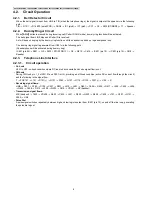
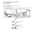
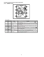
When the bell signal is input from LINE to T/R (when the telephone rings), the signal is output at the speaker via the following
path :
T/R
R1/C1
D1/LED1 (small PCB)
D3/D4
IC1 (pin8)
IC1 (pin5)
PC1
C5
SW2 (R7/R8/R9)
T1
Speaker
4.2.2.
Dummy Ringer Circuit
When
{
AOH
}
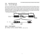
button is pressed during incoming call (Caller ID AOH mode), dummy ring function will be activated.
The bell signal from LINE stops and Caller ID is received.
Set will keep on ringing by the dummy ring function until the handset is picked up / speakerphone is on.
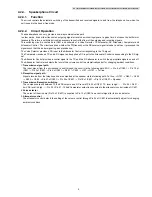
The dummy ring signal is generated from IC801 via the following path :
(Speakerphone will be activated during dummy ring)
IC801 (pin 89)
R901
Q2
SW2 ( R11/R12/R13 )
C8
R615
C616
IC601 (pin 19)
IC601 (pin 15)
C618
Speaker
4.2.3.
Telephone Line Interface
4.2.3.1.
Circuit operation
•
On hook
Q101 is OFF, on-hook condition where DC loop is disconnected and voice signal flow is cut.
•
Off hook
During Off-Hook, pin 1_3 of SW101 and Q101 is ON, providing an off-hook condition (active DC current flow through the circuit)
and the following is the signal flow :
T
POS101
L101
D101(+)
Q101
R180
Q107
R119
D103
D101(-)
L102
R
•
Receiving signal flows:
LINE
Q101
R180
C109
C401
R401
L412
L401
Q401
C404
R405
R417
L405
C405
L406
Q402
C408
R413
L409
Q403
C410
VR401
SP (handset)
•
Transmission signal flows:
MIC (handset)
C422
VR402
R423
C425
L421
R430
Q422
R429
C429
L107
Q107
Q101
R180
LINE
•
Pulse Dial
A pulse signal switches repeatedly between high and low logic is output from IC801 (pin 73), on and off the line loop, generating
the pulse dial signal.


